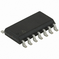
ATTINY24V-10SSU Atmel, ATTINY24V-10SSU Datasheet - Page 166

ATTINY24V-10SSU
Manufacturer Part Number
ATTINY24V-10SSU
Description
IC MCU AVR 2K FLASH 10MHZ 14SOIC
Manufacturer
Atmel
Series
AVR® ATtinyr
Specifications of ATTINY24V-10SSU
Core Processor
AVR
Core Size
8-Bit
Speed
10MHz
Connectivity
USI
Peripherals
Brown-out Detect/Reset, POR, PWM, Temp Sensor, WDT
Number Of I /o
12
Program Memory Size
2KB (1K x 16)
Program Memory Type
FLASH
Eeprom Size
128 x 8
Ram Size
128 x 8
Voltage - Supply (vcc/vdd)
1.8 V ~ 5.5 V
Data Converters
A/D 8x10b
Oscillator Type
Internal
Operating Temperature
-40°C ~ 85°C
Package / Case
14-SOIC (3.9mm Width), 14-SOL
Processor Series
ATTINY2x
Core
AVR8
Data Bus Width
8 bit
Data Ram Size
128 B
Interface Type
SPI
Maximum Clock Frequency
20 MHz
Number Of Programmable I/os
12
Number Of Timers
2
Operating Supply Voltage
1.8 V to 5.5 V
Maximum Operating Temperature
+ 85 C
Mounting Style
SMD/SMT
Minimum Operating Temperature
- 40 C
On-chip Adc
10 bit
For Use With
ATSTK600-DIP40 - STK600 SOCKET/ADAPTER 40-PDIP770-1007 - ISP 4PORT ATMEL AVR MCU SPI/JTAG770-1004 - ISP 4PORT FOR ATMEL AVR MCU SPIATAVRISP2 - PROGRAMMER AVR IN SYSTEMATSTK505 - ADAPTER KIT FOR 14PIN AVR MCU
Lead Free Status / RoHS Status
Lead free / RoHS Compliant
Available stocks
Company
Part Number
Manufacturer
Quantity
Price
Company:
Part Number:
ATTINY24V-10SSU
Manufacturer:
MICROCHIP
Quantity:
5 566
Part Number:
ATTINY24V-10SSU
Manufacturer:
ATMEL/爱特梅尔
Quantity:
20 000
- Current page: 166 of 238
- Download datasheet (5Mb)
Table 19-12. Serial Programming Instruction Set (Continued)
Notes:
Figure 19-2. Serial Programming Instruction example
166
Instruction/Operation
Write Instructions
Write Program Memory Page
Write EEPROM Memory
Write EEPROM Memory Page (page access)
Write Lock bits
Write Fuse bits
Write Fuse High bits
Write Extended Fuse Bits
Byte 1
1. Not all instructions are applicable for all parts.
2. a = address
3. Bits are programmed ‘0’, unprogrammed ‘1’.
4. To ensure future compatibility, unused Fuses and Lock bits should be unprogrammed (‘1’) .
5. Refer to the correspondig section for Fuse and Lock bits, Calibration and Signature bytes and Page size.
6. Instructions accessing program memory use a word address. This address may be random within the page range.
7. See http://www.atmel.com/avr for Application Notes regarding programming and programmers.
ATtiny24/44/84
Load Program Memory Page (High/Low Byte)/
Load EEPROM Memory Page (page access)
Bit 15 B
(6)
Byte 2
Adr M M S S B
A
(1)
Byte 3
Adr LSB
Page Offset
0
Serial Programming Instruction
Byte 4
Byte 1
$4C
$C0
$C2
$AC
$AC
$AC
$AC
Program Memory/
EEPROM Memory
Page Buffer
Page N-1
Page 0
Page 1
Page 2
Byte 1
adr MSB
Byte 2
$E0
$A0
$A8
$A4
$00
$00
Instruction Format
Page Number
Bit 15 B
Write Program Memory Page/
Write EEPROM Memory Page
Byte 2
Adr MSB
adr LSB
adr LSB
adr LSB
Byte 3
$00
$00
$00
$00
Byte 3
A A dr r L L SB B
0
data byte in
data byte in
data byte in
data byte in
data byte in
8006K–AVR–10/10
Byte4
$00
$00
Byte 4
Related parts for ATTINY24V-10SSU
Image
Part Number
Description
Manufacturer
Datasheet
Request
R

Part Number:
Description:
IC MCU AVR 2K FLASH 10MHZ 20-QFN
Manufacturer:
Atmel
Datasheet:

Part Number:
Description:
IC MCU AVR 2K FLASH 10MHZ 14-DIP
Manufacturer:
Atmel
Datasheet:

Part Number:
Description:
MCU AVR 2KB FLASH 10MHZ 14SOIC
Manufacturer:
Atmel
Datasheet:

Part Number:
Description:
MCU AVR 2KB FLASH 10MHZ 20QFN
Manufacturer:
Atmel
Datasheet:

Part Number:
Description:
8-bit Avr Microcontroller With 2/4/8k Bytes Insystem Programmable Flash
Manufacturer:
ATMEL Corporation
Datasheet:

Part Number:
Description:
8-bit Microcontrollers - MCU Microcontroller
Manufacturer:
Atmel

Part Number:
Description:
Manufacturer:
Atmel Corporation
Datasheet:

Part Number:
Description:
Manufacturer:
Atmel Corporation
Datasheet:

Part Number:
Description:
IC MCU AVR 2K FLASH 20MHZ 20-QFN
Manufacturer:
Atmel
Datasheet:

Part Number:
Description:
IC MCU AVR 2K FLASH 20MHZ 14SOIC
Manufacturer:
Atmel
Datasheet:

Part Number:
Description:
MCU AVR 2K FLASH 15MHZ 20-QFN
Manufacturer:
Atmel
Datasheet:

Part Number:
Description:
IC MCU AVR 2K FLASH 20MHZ 14-DIP
Manufacturer:
Atmel
Datasheet:


