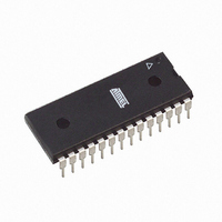
ATMEGA168V-10PU Atmel, ATMEGA168V-10PU Datasheet - Page 283

ATMEGA168V-10PU
Manufacturer Part Number
ATMEGA168V-10PU
Description
IC AVR MCU 16K 10MHZ 28DIP
Manufacturer
Atmel
Series
AVR® ATmegar
Datasheets
1.ATAVRTS2080B.pdf
(378 pages)
2.ATMEGA48-20AU.pdf
(35 pages)
3.ATMEGA168-20AU.pdf
(359 pages)
Specifications of ATMEGA168V-10PU
Core Processor
AVR
Core Size
8-Bit
Speed
10MHz
Connectivity
I²C, SPI, UART/USART
Peripherals
Brown-out Detect/Reset, POR, PWM, WDT
Number Of I /o
23
Program Memory Size
16KB (8K x 16)
Program Memory Type
FLASH
Eeprom Size
512 x 8
Ram Size
1K x 8
Voltage - Supply (vcc/vdd)
1.8 V ~ 5.5 V
Data Converters
A/D 6x10b
Oscillator Type
Internal
Operating Temperature
-40°C ~ 85°C
Package / Case
28-DIP (0.300", 7.62mm)
Processor Series
ATMEGA16x
Core
AVR8
Data Bus Width
8 bit
Data Ram Size
1 KB
Interface Type
2-Wire, SPI, USART, Serial
Maximum Clock Frequency
10 MHz
Number Of Programmable I/os
23
Number Of Timers
3 bit
Operating Supply Voltage
1.8 V to 5.5 V
Maximum Operating Temperature
+ 85 C
Mounting Style
Through Hole
3rd Party Development Tools
EWAVR, EWAVR-BL
Minimum Operating Temperature
- 40 C
On-chip Adc
10 bit, 6 Channel
Package
28PDIP
Device Core
AVR
Family Name
ATmega
Maximum Speed
10 MHz
Controller Family/series
AVR MEGA
No. Of I/o's
23
Eeprom Memory Size
512Byte
Ram Memory Size
1KB
Cpu Speed
10MHz
Rohs Compliant
Yes
For Use With
ATSTK600-TQFP32 - STK600 SOCKET/ADAPTER 32-TQFPATSTK600 - DEV KIT FOR AVR/AVR32770-1007 - ISP 4PORT ATMEL AVR MCU SPI/JTAGATAVRDRAGON - KIT DRAGON 32KB FLASH MEM AVRATAVRISP2 - PROGRAMMER AVR IN SYSTEMATJTAGICE2 - AVR ON-CHIP D-BUG SYSTEM
Lead Free Status / RoHS Status
Lead free / RoHS Compliant
- Current page: 283 of 359
- Download datasheet (3Mb)
25.2.1
25.3
25.3.1
25.3.2
25.3.3
2545E–AVR–02/05
Signature Bytes
Latching of Fuses
ATmega48 Signature Bytes
ATmega88 Signature Bytes
ATmega168 Signature Bytes
Table 25-7.
Note:
The status of the Fuse bits is not affected by Chip Erase. Note that the Fuse bits are locked if
Lock bit1 (LB1) is programmed. Program the Fuse bits before programming the Lock bits.
The fuse values are latched when the device enters programming mode and changes of the
fuse values will have no effect until the part leaves Programming mode. This does not apply to
the EESAVE Fuse which will take effect once it is programmed. The fuses are also latched on
Power-up in Normal mode.
All Atmel microcontrollers have a three-byte signature code which identifies the device. This
code can be read in both serial and parallel mode, also when the device is locked. The three
bytes reside in a separate address space.
1. 0x000: 0x1E (indicates manufactured by Atmel).
2. 0x001: 0x92 (indicates 4KB Flash memory).
3. 0x002: 0x05 (indicates ATmega48 device when 0x001 is 0x92).
1. 0x000: 0x1E (indicates manufactured by Atmel).
2. 0x001: 0x93 (indicates 8KB Flash memory).
3. 0x002: 0x0A (indicates ATmega88 device when 0x001 is 0x93).
1. 0x000: 0x1E (indicates manufactured by Atmel).
2. 0x001: 0x94 (indicates 16KB Flash memory).
3. 0x002: 0x06 (indicates ATmega168 device when 0x001 is 0x94).
Low Fuse Byte
CKDIV8
CKOUT
SUT1
SUT0
CKSEL3
CKSEL2
CKSEL1
CKSEL0
1. The default value of SUT1..0 results in maximum start-up time for the default clock source.
2. The default setting of CKSEL3..0 results in internal RC Oscillator @ 8 MHz. See
3. The CKOUT Fuse allows the system clock to be output on PORTB0. See
4. See
(3)
(4)
See
page 31
on page 34
Fuse Low Byte
Table 6-9 on page 32
”System Clock Prescaler” on page 34
for details.
for details.
Bit No
7
6
5
4
3
2
1
0
for details.
Description
Divide clock by 8
Clock output
Select start-up time
Select start-up time
Select Clock source
Select Clock source
Select Clock source
Select Clock source
for details.
ATmega48/88/168
Default Value
0 (programmed)
1 (unprogrammed)
1 (unprogrammed)
0 (programmed)
0 (programmed)
0 (programmed)
1 (unprogrammed)
0 (programmed)
”Clock Output Buffer”
(1)
(2)
(2)
(2)
Table 6-8 on
(1)
(2)
283
Related parts for ATMEGA168V-10PU
Image
Part Number
Description
Manufacturer
Datasheet
Request
R

Part Number:
Description:
Manufacturer:
Atmel Corporation
Datasheet:

Part Number:
Description:
Manufacturer:
Atmel Corporation
Datasheet:

Part Number:
Description:
Manufacturer:
ATMEL Corporation
Datasheet:

Part Number:
Description:
IC AVR MCU 16K 20MHZ 32TQFP
Manufacturer:
Atmel
Datasheet:

Part Number:
Description:
IC AVR MCU 16K 20MHZ 32-QFN
Manufacturer:
Atmel
Datasheet:

Part Number:
Description:
IC AVR MCU 16K 20MHZ 28DIP
Manufacturer:
Atmel
Datasheet:

Part Number:
Description:
MCU AVR 16K FLASH 15MHZ 32-TQFP
Manufacturer:
Atmel
Datasheet:

Part Number:
Description:
MCU AVR 16K FLASH 15MHZ 32-QFN
Manufacturer:
Atmel
Datasheet:

Part Number:
Description:
IC AVR MCU 16K 20MHZ 32TQFP
Manufacturer:
Atmel
Datasheet:

Part Number:
Description:
MCU AVR 16KB FLASH 20MHZ 32QFN
Manufacturer:
Atmel
Datasheet:

Part Number:
Description:
MCU AVR 16KB FLASH 20MHZ 32TQFP
Manufacturer:
Atmel
Datasheet:

Part Number:
Description:
IC MCU AVR 16K FLASH 32-QFN
Manufacturer:
Atmel
Datasheet:


