1206SFS250F/32-2 Tyco Electronics, 1206SFS250F/32-2 Datasheet - Page 2
1206SFS250F/32-2
Manufacturer Part Number
1206SFS250F/32-2
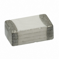
Description
FUSE 2.5A 32V SLOW SMD 1206
Manufacturer
Tyco Electronics
Series
1206SFSr
Datasheet
1.1206SFS200F63-2.pdf
(4 pages)
Specifications of 1206SFS250F/32-2
Fuse Type
Slow Blow, Time Lag
Voltage - Rated
32VDC
Current
2.5A
Package / Case
1206 (3216 Metric)
Size / Dimension
0.126" L x 0.063" W x 0.038" H (3.20mm x 1.60mm x 0.97mm)
Mounting Type
Surface Mount
Operating Temperature
-55°C ~ 125°C
Dc Cold Resistance
0.07 Ohm
Melting I²t
0.9
Voltage Rating Vdc
32V
Fuse Current
2.5A
Breaking Capacity
50A
External Depth
0.97mm
External Length / Height
3.2mm
External Width
1.6mm
Fuse Type Blowing Characteristic
Slow Blow
Package /
RoHS Compliant
Lead Free Status / RoHS Status
Lead free / RoHS Compliant
Color
-
Lead Free Status / RoHS Status
Lead free / RoHS Compliant
Other names
451674-000


Table FS1 - Clear Time Characteristics for Slow Blow Fuses
% of Current Rating
Table FS2 - Interrupt Ratings for Slow Blow Fuses
Interrupt Ratings:
1A – 5.5A
6A – 8.0A
Table FS3 - Typical Electrical Characteristics, Dimensions and Recommended Pad Layout for Slow Blow Fuses
1206 (3216mm) Slow Blow Fuses
Table FS4 - Environmental and Material Specifications for Slow Blow Fuses
Shape and
Dimensions
Inch (mm)
Recommended
Pad layout
Inch (mm)
Environmental Specifications
Operating Temperature
Mechanical Vibration
Mechanical Shock
Thermal Shock
Resistance to Soldering Heat
Solderbility
Moisture Resistance
Salt Spray
Material Specifications
Construction Body Material
Termination Material
Fuse Element
Terminal Strength: Hanging test
100%
200%
300%
800%
0.063 0.008
(1.60 0.20)
4 hours (min.)
1 second (min.)
0.1 second (min.)
0.002 second (min.) 0.05 seconds (max.)
0.057
(1.45)
0.020 0.010
(0.51 0.25)
0.059
(1.50)
0.173
(4.40)
Clear time at 25 C
50A @ rated voltage
60A @ rated voltage
0.126 0.008
(3.20 0.20)
-55ºC to +125ºC
Withstands 5-3000 Hz at 30 Gs when evaluated per Method 204 of MIL-STD-202
Withstands 1500 Gs, 0.5 millisecond half-sine pulses when evaluated per Method 213 of MIL-STD-202
Withstands 100 cycles from -65ºC to +125ºC when evaluated per Method 107 of MIL-STD-202
Withstands 60 seconds at +260ºC when evaluated per Method 210 of MIL-STD-202
Meets 95% minimum coverage requirement when evaluated per Method 208 of MIL-STD-202
Withstands 10 cycles when evaluated per Method 106 of MIL-STD-202
Withstands 48-hour exposure when evaluated per Method 101 of MIL-STD-202
Ceramic
Silver, Nickel, Tin
Silver
1.5kg, 30 seconds
120 seconds (max.)
3 seconds (max.)
0.071
(1.80)
0.038 0.008
(0.97 0.20)
* Measured at 10% of rated current and 25 C
†
1206SFS100F/63
1206SFS125F/63
1206SFS150F/63
1206SFS200F/63
1206SFS250F/32
1206SFS300F/32
1206SFS350F/32
1206SFS400F/32
1206SFS450F/32
1206SFS500F/32
1206SFS550F/24
1206SFS600F/24
1206SFS700F/24
1206SFS800F/24
Melting I
Number
Part
2
t at 0.001 sec clear time
Current
Rated
(A)
1.0
1.25
1.5
2.0
2.5
3.0
3.5
4.0
4.5
5.0
5.5
6.0
7.0
8.0
Typical Electrical
Characteristics
Cold DCR
Nominal
0.360
0.200
0.150
0.082
0.070
0.032
0.028
0.024
0.020
0.016
0.014
0.011
0.010
0.009
( )
*
*
Nominal
(A
10.00
16.90
0.11
0.22
0.23
0.63
0.90
1.20
1.60
2.20
3.60
5.30
6.40
8.50
2
I
sec)
2
t
†
Voltage
(V
63
32
24
DC
)
70
Related parts for 1206SFS250F/32-2
Image
Part Number
Description
Manufacturer
Datasheet
Request
R

Part Number:
Description:
FUSE 7.0A 24V SLOW SMD 1206
Manufacturer:
Tyco Electronics
Datasheet:
Part Number:
Description:
FUSE 8.0A 24V SLOW SMD 1206
Manufacturer:
Tyco Electronics
Datasheet:
Part Number:
Description:
FUSE 1.0A 63V SLOW SMD 1206
Manufacturer:
Tyco Electronics
Datasheet:
Part Number:
Description:
FUSE 2.0A 63V SLOW SMD 1206
Manufacturer:
Tyco Electronics
Datasheet:
Part Number:
Description:
FUSE 5.0A 32V SLOW SMD 1206
Manufacturer:
Tyco Electronics
Datasheet:
Part Number:
Description:
FUSE 1.5A 63V SLOW SMD 1206
Manufacturer:
Tyco Electronics
Datasheet:
Part Number:
Description:
FUSE 3.0A 32V SLOW SMD 1206
Manufacturer:
Tyco Electronics
Datasheet:
Part Number:
Description:
FUSE 6.0A 24V SLOW SMD 1206
Manufacturer:
Tyco Electronics
Datasheet:
Part Number:
Description:
FUSE 4.0A 32V SLOW SMD 1206
Manufacturer:
Tyco Electronics
Datasheet:
Part Number:
Description:
FUSE 1.25A 63V SLOW SMD 1206
Manufacturer:
Tyco Electronics
Datasheet:
Part Number:
Description:
FUSE 3.5A 32V SLOW SMD 1206
Manufacturer:
Tyco Electronics
Datasheet:
Part Number:
Description:
FUSE 5.5A 24V SLOW SMD 1206
Manufacturer:
Tyco Electronics
Datasheet:
Part Number:
Description:
TPE / El Fuse
Manufacturer:
Tyco Electronics
Datasheet:

Part Number:
Description:
Battery Interconnection System for Portable Electronics; BU CONN FS6 8POS DIP TYPE ASSY ( AMP )
Manufacturer:
Tyco Electronics