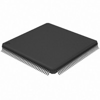
AT32UC3A3128-ALUT Atmel, AT32UC3A3128-ALUT Datasheet - Page 72

AT32UC3A3128-ALUT
Manufacturer Part Number
AT32UC3A3128-ALUT
Description
IC MCU 128KB FLASH 144LQFP
Manufacturer
Atmel
Series
AVR®32 UC3r
Specifications of AT32UC3A3128-ALUT
Core Processor
AVR
Core Size
32-Bit
Speed
66MHz
Connectivity
EBI/EMI, I²C, IrDA, MMC, SPI, SSC, UART/USART, USB OTG
Peripherals
Brown-out Detect/Reset, DMA, POR, WDT
Number Of I /o
110
Program Memory Size
128KB (128K x 8)
Program Memory Type
FLASH
Ram Size
128K x 8
Voltage - Supply (vcc/vdd)
1.65 V ~ 1.95 V
Data Converters
A/D 8x10b
Oscillator Type
Internal
Operating Temperature
-40°C ~ 85°C
Package / Case
144-LQFP
Processor Series
AT32UC3x
Core
AVR32
Data Bus Width
32 bit
Data Ram Size
96 KB
Interface Type
IrDA/SCI/SCIF/UDI
Maximum Clock Frequency
66 MHz
Number Of Timers
3
Operating Supply Voltage
3 V to 3.6 V
Maximum Operating Temperature
+ 85 C
Mounting Style
SMD/SMT
3rd Party Development Tools
EWAVR32, EWAVR32-BL, KSK-EVK1100-PL
Development Tools By Supplier
ATAVRDRAGON, ATSTK500, ATSTK600, ATAVRISP2, ATAVRONEKIT, ATEXTWIFI, ATEVK1104
Minimum Operating Temperature
- 40 C
Controller Family/series
AT32UC3A
No. Of I/o's
109
Ram Memory Size
32KB
Cpu Speed
66MHz
No. Of Timers
1
Rohs Compliant
Yes
For Use With
ATEVK1104 - KIT DEV/EVAL FOR AVR32 AT32UC3AATAVRONEKIT - KIT AVR/AVR32 DEBUGGER/PROGRMMRATEVK1100 - KIT DEV/EVAL FOR AVR32 AT32UC3A
Lead Free Status / RoHS Status
Lead free / RoHS Compliant
Eeprom Size
-
Lead Free Status / Rohs Status
Lead free / RoHS Compliant
Available stocks
Company
Part Number
Manufacturer
Quantity
Price
Company:
Part Number:
AT32UC3A3128-ALUT
Manufacturer:
Atmel
Quantity:
135
10.14 Flash Memory Characteristics
Table 10-39. Flash Operating Frequency
Table 10-40. Parts Programming Time
Table 10-41. Flash Parameters
32072C–AVR32–2010/03
Symbol
F
Symbol
T
T
T
Symbol
N
N
T
FOP
FPP
FFP
FCE
FDR
FARRAY
FFUSE
Parameter
Flash Operating Frequency
Parameter
Page Programming Time
Fuse Programming Time
Chip erase Time
Parameter
Flash Array Write/Erase cycle
General Purpose Fuses write cycle
Flash Data Retention Time
The following table gives the device maximum operating frequency depending on the field FWS
of the Flash FSR register. This field defines the number of wait states required to access the
Flash Memory. Flash operating frequency equals the CPU/HSB frequency.
Conditions
FWS = 0
FWS = 1
Conditions
Conditions
Min.
Min.
Min.
AT32UC3A3/A4
Typ.
Typ.
Typ.
0.5
15
4
8
100K
Max.
Max.
Max.
1000
36
66
MHz
MHz
Unit
Unit
Unit
cycle
cycle
year
ms
ms
ms
72


