Z8F4822AR020EC Zilog, Z8F4822AR020EC Datasheet - Page 211
Z8F4822AR020EC
Manufacturer Part Number
Z8F4822AR020EC
Description
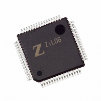
IC ENCORE MCU FLASH 48K 64LQFP
Manufacturer
Zilog
Series
Encore!® XP®r
Specifications of Z8F4822AR020EC
Core Processor
Z8
Core Size
8-Bit
Speed
20MHz
Connectivity
I²C, IrDA, SPI, UART/USART
Peripherals
Brown-out Detect/Reset, DMA, POR, PWM, WDT
Number Of I /o
46
Program Memory Size
48KB (48K x 8)
Program Memory Type
FLASH
Ram Size
4K x 8
Voltage - Supply (vcc/vdd)
3 V ~ 3.6 V
Data Converters
A/D 12x10b
Oscillator Type
Internal
Operating Temperature
-40°C ~ 105°C
Package / Case
64-LQFP
Lead Free Status / RoHS Status
Contains lead / RoHS non-compliant
Eeprom Size
-
Other names
269-3289
Available stocks
Company
Part Number
Manufacturer
Quantity
Price


PS019921-0308
START
DEBUG Mode
OCD Data Format
The operating characteristics of the Z8 Encore! XP
mode are:
•
•
•
•
•
Entering DEBUG Mode
The device enters DEBUG mode following any of the following operations:
•
•
•
Exiting DEBUG Mode
The device exits DEBUG mode following any of the following operations:
•
•
•
•
•
The OCD interface uses the asynchronous data format defined for RS-232. Each character
is transmitted as 1 Start bit, 8 data bits (least-significant bit first), and 1 Stop bit
(see
D0
The eZ8 CPU fetch unit stops, idling the eZ8 CPU, unless directed by the OCD to
execute specific instructions.
The system clock operates unless in STOP mode.
All enabled on-chip peripherals operate unless in STOP mode.
Automatically exits HALT mode.
Constantly refreshes the Watchdog Timer, if enabled.
Writing the DBGMODE bit in the OCD Control Register to 1 using the OCD interface.
eZ8 CPU execution of a BRK (Breakpoint) instruction (when enabled).
If the DBG pin is Low when the device exits Reset, the On-Chip Debugger
automatically puts the device into DEBUG mode.
Clearing the DBGMODE bit in the OCD Control Register to 0.
Power-On Reset
Voltage Brownout reset
Asserting the RESET pin Low to initiate a Reset.
Driving the DBG pin Low while the device is in STOP mode initiates a system reset.
Figure
D1
38).
Figure 38. OCD Data Format
D2
D3
D4
®
D5
F64XX Series devices in DEBUG
Z8 Encore! XP
D6
Product Specification
D7
®
On-Chip Debugger
F64XX Series
STOP
197
Related parts for Z8F4822AR020EC
Image
Part Number
Description
Manufacturer
Datasheet
Request
R

Part Number:
Description:
Communication Controllers, ZILOG INTELLIGENT PERIPHERAL CONTROLLER (ZIP)
Manufacturer:
Zilog, Inc.
Datasheet:

Part Number:
Description:
KIT DEV FOR Z8 ENCORE 16K TO 64K
Manufacturer:
Zilog
Datasheet:

Part Number:
Description:
KIT DEV Z8 ENCORE XP 28-PIN
Manufacturer:
Zilog
Datasheet:

Part Number:
Description:
DEV KIT FOR Z8 ENCORE 8K/4K
Manufacturer:
Zilog
Datasheet:

Part Number:
Description:
KIT DEV Z8 ENCORE XP 28-PIN
Manufacturer:
Zilog
Datasheet:

Part Number:
Description:
DEV KIT FOR Z8 ENCORE 4K TO 8K
Manufacturer:
Zilog
Datasheet:
Part Number:
Description:
CMOS Z8 microcontroller. ROM 16 Kbytes, RAM 256 bytes, speed 16 MHz, 32 lines I/O, 3.0V to 5.5V
Manufacturer:
Zilog, Inc.
Datasheet:
Part Number:
Description:
Low-cost microcontroller. 512 bytes ROM, 61 bytes RAM, 8 MHz
Manufacturer:
Zilog, Inc.
Datasheet:
Part Number:
Description:
Z8 4K OTP Microcontroller
Manufacturer:
Zilog, Inc.
Datasheet:
Part Number:
Description:
CMOS SUPER8 ROMLESS MCU
Manufacturer:
Zilog, Inc.
Datasheet:
Part Number:
Description:
SL1866 CMOSZ8 OTP Microcontroller
Manufacturer:
Zilog, Inc.
Datasheet:
Part Number:
Description:
SL1866 CMOSZ8 OTP Microcontroller
Manufacturer:
Zilog, Inc.
Datasheet:
Part Number:
Description:
OTP (KB) = 1, RAM = 125, Speed = 12, I/O = 14, 8-bit Timers = 2, Comm Interfaces Other Features = Por, LV Protect, Voltage = 4.5-5.5V
Manufacturer:
Zilog, Inc.
Datasheet:
Part Number:
Description:
Manufacturer:
Zilog, Inc.
Datasheet: