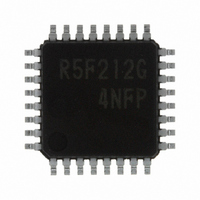
R5F212G4SNFP#U0 Renesas Electronics America, R5F212G4SNFP#U0 Datasheet - Page 30

R5F212G4SNFP#U0
Manufacturer Part Number
R5F212G4SNFP#U0
Description
IC R8C/2G MCU FLASH 32LQFP
Manufacturer
Renesas Electronics America
Series
R8C/2x/2Gr
Datasheet
1.R5F212G4SDFPU0.pdf
(45 pages)
Specifications of R5F212G4SNFP#U0
Core Processor
R8C
Core Size
16/32-Bit
Speed
8MHz
Connectivity
LIN, SIO, UART/USART
Peripherals
POR, PWM, Voltage Detect, WDT
Number Of I /o
27
Program Memory Size
16KB (16K x 8)
Program Memory Type
FLASH
Ram Size
512 x 8
Voltage - Supply (vcc/vdd)
2.2 V ~ 5.5 V
Oscillator Type
Internal
Operating Temperature
-20°C ~ 85°C
Package / Case
32-LQFP
Lead Free Status / RoHS Status
Lead free / RoHS Compliant
Eeprom Size
-
Data Converters
-
Available stocks
Company
Part Number
Manufacturer
Quantity
Price
R8C/2G Group
Rev.1.00
REJ03B0223-0100
Table 5.8
NOTE:
Table 5.9
NOTES:
Table 5.10
NOTE:
Table 5.11
NOTES:
Vref
Vcref
Vcin
Vofs
Tcrsp
fOCO-F
fOCO-S
−
−
t
t
d(P-R)
d(R-S)
Symbol
Symbol
Symbol
Symbol
1. The measurement condition is T
1. The measurement condition is T
2. These standard values show when the HRA1 register is set to the value before shipment and the HRA2 register is set to 00h.
3. These standard values show when the correction value in the FRA6 register is written into the HRA1 register.
1. V
1. The measurement condition is V
2. Waiting time until the internal power supply generation circuit stabilizes during power-on.
3. Time until system clock supply starts after the interrupt is acknowledged to exit stop mode.
CC
Apr 04, 2008
= 2.2 to 5.5 V, T
Internal reference voltage
External input reference voltage
External comparison voltage input
range
Input offset voltage
Response time
High-speed on-chip oscillator frequency
temperature • supply voltage dependence
Low-speed on-chip oscillator frequency
Oscillation stability time
Self power consumption at oscillation
Time for internal power supply stabilization during
power-on
STOP exit time
Comparator Electrical Characteristics
High-speed On-Chip Oscillator Circuit Electrical Characteristics
Low-speed On-Chip Oscillator Circuit Electrical Characteristics
Power Supply Circuit Timing Characteristics
(2)
opr
Parameter
(3)
Page 28 of 41
= −20 to 85°C (N version) / −40 to 85°C (D version), unless otherwise specified.
Parameter
Parameter
Parameter
opr
opr
CC
= −20 to 85°C (N version) / −40 to 85°C (D version), unless otherwise specified.
= −20 to 85°C (N version) / −40 to 85°C (D version), unless otherwise specified.
= 2.2 to 5.5 V and T
V
V
V
T
V
opr
CC
CC
CC
CC
= −40 to 85°C
= 2.2 V to 5.5 V, T
= 2.2 V to 5.5 V,
= 2.2 V to 4.0 V
= 4.0 V to 5.5 V
opr
V
T
V
T
V
T
V
T
V
T
opr
opr
opr
opr
opr
= 25°C.
CC
CC
CC
CC
CC
Condition
= 0 to 60°C
= −20 to 85°C
= −40 to 85°C
= −20 to 85°C
= −40 to 85°C
= 4.75 V to 5.25 V
= 2.7 V to 5.5 V
= 2.7 V to 5.5 V
= 2.2 V to 5.5 V
= 2.2 V to 5.5 V
V
CC
Condition
= 5.0 V, T
opr
Condition
Condition
(2)
= 25°C
(2)
(2)
(3)
(3)
opr
= 25°C
Min.
1.15
−0.3
0.5
0.5
−
−
−
Min.
7.76
7.68
7.44
7.04
6.8
Min.
Min.
30
5. Electrical Characteristics
−
−
1
−
Standard
Standard
1.25
1.25
Typ.
20
−
−
−
4
Typ.
Standard
Standard
8
8
8
8
8
Typ.
Typ.
125
10
15
−
−
V
V
V
CC
CC
CC
Max.
1.35
120
Max.
8.24
8.32
8.32
8.96
2000
9.2
Max.
Max.
−
−
250
100
150
− 1.1
− 1.5
+ 0.3
−
MHz
MHz
MHz
MHz
MHz
Unit
Unit
Unit
Unit
kHz
mV
µA
µs
µs
µs
µs
V
V
V
V


