M38039G4HSP#U0 Renesas Electronics America, M38039G4HSP#U0 Datasheet - Page 49
M38039G4HSP#U0
Manufacturer Part Number
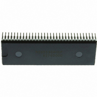
M38039G4HSP#U0
Description
IC 740/3803 MCU QZROM 64DIP
Manufacturer
Renesas Electronics America
Series
740/38000r
Datasheet
1.M38039G4HHPU0.pdf
(105 pages)
Specifications of M38039G4HSP#U0
Core Processor
740
Core Size
8-Bit
Speed
16.8MHz
Connectivity
SIO, UART/USART
Peripherals
LED, PWM, WDT
Number Of I /o
56
Program Memory Size
16KB (16K x 8)
Program Memory Type
QzROM
Ram Size
2K x 8
Voltage - Supply (vcc/vdd)
1.8 V ~ 5.5 V
Data Converters
A/D 16x10b; D/A 2x8b
Oscillator Type
Internal
Operating Temperature
-20°C ~ 85°C
Package / Case
64-SDIP (0.750", 19.05mm)
Lead Free Status / RoHS Status
Lead free / RoHS Compliant
Eeprom Size
-


3803 Group (Spec.H QzROM version)
REJ03B0166-0113 Rev.1.13
Page 47 of 100
(2) Asynchronous Serial I/O (UART) Mode
Clock asynchronous serial I/O mode (UART) can be selected by
clearing the serial I/O1 mode selection bit (b6) of the serial I/O1
control register to “0”.
Eight serial data transfer formats can be selected, and the transfer
formats used by a transmitter and receiver must be identical.
Fig 38. Block diagram of UART serial I/O1
Fig 39. Operation of UART serial I/O1
Transmit buffer register 1
Receive buffer register 1
(f(X
CIN
Serial input R
) in low-speed mode)
P4
P4
P4
6
receive clock
Serial output
4
5
/S
Transmit or
/R
write signal
/T
read signal
f(X
CLK1
X
X
D
D
IN
Notes 1: Error flag detection occurs at the same time that the RBF flag becomes “1” (at 1st stop bit, during reception).
1
1
)
T
X
X
D
D
1
1
2: As the transmit interrupt (TI), when either the TBE or TSC flag becomes “1”, can be selected to occur depending on the setting of the transmit interrupt source
3: The receive interrupt (RI) is set when the RBF flag becomes “1”.
4: After data is written to the transmit buffer when TSC=1, 0.5 to 1.5 cycles of the data shift cycle are necessary until changing to TSC=0.
selection bit (TIC) of the serial I/O1 control register.
ST detector
BRG count source selection bit
TBE=0
TSC=0
TBE=1
1/4
ST
ST
Character length selection bit
7 bits
8 bits
Character length selection bit
Aug 21, 2009
D
D
0
0
OE
Serial I/O1 synchronous clock selection bit
D
D
1
TBE=0
1
1 start bit
7 or 8 data bit
1 or 0 parity bit
1 or 2 stop bit (s)
PE FE
Receive buffer register 1
Receive shift register 1
ST/SP/PA generator
Frequency division ratio 1/(n+1)
Data bus
Data bus
Baud rate generator
Transmit buffer register 1
SP detector
Transmit shift register 1
Address 0018
Address 001C
The transmit and receive shift registers each have the buffer
register 1, but the two buffer registers have the same address in a
memory. Since the shift register cannot be written to or read from
directly, transmit data is written to the transmit buffer register 1,
and receive data is read from the receive buffer register 1.
The transmit buffer register 1 can also hold the next data to be
transmitted, and the receive buffer register 1 can hold a character
while the next character is being received.
Address 0018
16
RBF=1
16
1/16
SP
SP
TBE=1
Serial I/O1 control register
Clock control circuit
ST
16
ST
Transmit interrupt source selection bit
Receive buffer full flag (RBF)
Receive interrupt request (RI)
Serial I/O1 status register
D
D
0
0
RBF=0
D
D
1
1
Address 001A
1/16
Transmit buffer empty flag (TBE)
Transmit shift
completion flag (TSC)
Generated at 2nd bit in 2-stop-bit mode
UART1 control register
Transmit interrupt request (TI)
16
Address 0019
Address 001B
16
TSC=1*
SP
16
RBF=1
SP
Related parts for M38039G4HSP#U0
Image
Part Number
Description
Manufacturer
Datasheet
Request
R

Part Number:
Description:
KIT STARTER FOR M16C/29
Manufacturer:
Renesas Electronics America
Datasheet:

Part Number:
Description:
KIT STARTER FOR R8C/2D
Manufacturer:
Renesas Electronics America
Datasheet:

Part Number:
Description:
R0K33062P STARTER KIT
Manufacturer:
Renesas Electronics America
Datasheet:

Part Number:
Description:
KIT STARTER FOR R8C/23 E8A
Manufacturer:
Renesas Electronics America
Datasheet:

Part Number:
Description:
KIT STARTER FOR R8C/25
Manufacturer:
Renesas Electronics America
Datasheet:

Part Number:
Description:
KIT STARTER H8S2456 SHARPE DSPLY
Manufacturer:
Renesas Electronics America
Datasheet:

Part Number:
Description:
KIT STARTER FOR R8C38C
Manufacturer:
Renesas Electronics America
Datasheet:

Part Number:
Description:
KIT STARTER FOR R8C35C
Manufacturer:
Renesas Electronics America
Datasheet:

Part Number:
Description:
KIT STARTER FOR R8CL3AC+LCD APPS
Manufacturer:
Renesas Electronics America
Datasheet:
Part Number:
Description:
KIT STARTER FOR RX610
Manufacturer:
Renesas Electronics America
Datasheet:

Part Number:
Description:
KIT STARTER FOR R32C/118
Manufacturer:
Renesas Electronics America
Datasheet:

Part Number:
Description:
KIT DEV RSK-R8C/26-29
Manufacturer:
Renesas Electronics America
Datasheet:

Part Number:
Description:
KIT STARTER FOR SH7124
Manufacturer:
Renesas Electronics America
Datasheet:

Part Number:
Description:
KIT STARTER FOR H8SX/1622
Manufacturer:
Renesas Electronics America
Datasheet:

Part Number:
Description:
KIT DEV FOR SH7203
Manufacturer:
Renesas Electronics America
Datasheet: