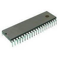
MC705C8ABE Freescale Semiconductor, MC705C8ABE Datasheet - Page 51

MC705C8ABE
Manufacturer Part Number
MC705C8ABE
Description
IC MCU 8BIT 42-SDIP
Manufacturer
Freescale Semiconductor
Series
HC05r
Datasheet
1.MC68HC705C8AB.pdf
(222 pages)
Specifications of MC705C8ABE
Core Processor
HC05
Core Size
8-Bit
Speed
2.1MHz
Connectivity
SCI, SPI
Peripherals
POR, WDT
Number Of I /o
24
Program Memory Size
8KB (8K x 8)
Program Memory Type
OTP
Ram Size
304 x 8
Voltage - Supply (vcc/vdd)
3 V ~ 5.5 V
Oscillator Type
Internal
Operating Temperature
0°C ~ 70°C
Package / Case
42-DIP (0.600", 15.24mm)
Processor Series
HC705C
Core
HC05
Data Bus Width
8 bit
Data Ram Size
304 B
Interface Type
SCI, SPI
Maximum Clock Frequency
2.1 MHz
Number Of Programmable I/os
24
Number Of Timers
1
Mounting Style
Through Hole
Lead Free Status / RoHS Status
Lead free / RoHS Compliant
Eeprom Size
-
Data Converters
-
Lead Free Status / Rohs Status
Details
Available stocks
Company
Part Number
Manufacturer
Quantity
Price
Company:
Part Number:
MC705C8ABE
Manufacturer:
Freescale Semiconductor
Quantity:
135
- Current page: 51 of 222
- Download datasheet (3Mb)
4.3.2 External Interrupt (IRQ)
MC68HC705C8A — Rev. 3
MOTOROLA
NOTE:
An interrupt signal on the IRQ pin latches an external interrupt request.
After completing the current instruction, the CPU tests these bits:
Setting the I bit in the CCR disables external interrupts.
If the IRQ latch is set and the I bit is clear, the CPU then begins the
interrupt sequence. The CPU clears the IRQ latch while it fetches the
interrupt vector, so that another external interrupt request can be latched
during the interrupt service routine. As soon as the I bit is cleared during
the return-from-interrupt (RTI) instruction, the CPU can recognize the
new interrupt request.
Figure 4-1
shows an external interrupt timing diagram for the interrupt line. The
timing diagram illustrates two treatments of the interrupt line to the
processor.
The internal interrupt latch is cleared in the first part of the interrupt
service routine. Therefore, a new external interrupt pulse could be
latched and serviced as soon as the I bit is cleared.
If the IRQ pin is not in use, connect it to the V
1. Two single pulses on the interrupt line are spaced far enough
2. Many interrupt lines are “wire-ORed” to the IRQ line. If the interrupt
•
•
Freescale Semiconductor, Inc.
For More Information On This Product,
IRQ latch
I bit in the CCR
apart to be serviced. The minimum time between pulses is a
function of the length of the interrupt service.
Once a pulse occurs, the next pulse normally should not occur
until an RTI occurs. This time (t
instruction cycles to the total number of cycles needed to complete
the service routine (not including the RTI instruction).
line remains low after servicing an interrupt, then the CPU
continues to recognize an interrupt.
shows an external interrupt functional diagram.
Go to: www.freescale.com
Interrupts
Figure 4-1
shows the logic for external interrupts.
ILIL
) is obtained by adding 19
DD
pin.
Interrupt Sources
Figure 4-2
Technical Data
Interrupts
Related parts for MC705C8ABE
Image
Part Number
Description
Manufacturer
Datasheet
Request
R
Part Number:
Description:
Manufacturer:
Freescale Semiconductor, Inc
Datasheet:
Part Number:
Description:
Manufacturer:
Freescale Semiconductor, Inc
Datasheet:
Part Number:
Description:
Manufacturer:
Freescale Semiconductor, Inc
Datasheet:
Part Number:
Description:
Manufacturer:
Freescale Semiconductor, Inc
Datasheet:
Part Number:
Description:
Manufacturer:
Freescale Semiconductor, Inc
Datasheet:
Part Number:
Description:
Manufacturer:
Freescale Semiconductor, Inc
Datasheet:
Part Number:
Description:
Manufacturer:
Freescale Semiconductor, Inc
Datasheet:
Part Number:
Description:
Manufacturer:
Freescale Semiconductor, Inc
Datasheet:
Part Number:
Description:
Manufacturer:
Freescale Semiconductor, Inc
Datasheet:
Part Number:
Description:
Manufacturer:
Freescale Semiconductor, Inc
Datasheet:
Part Number:
Description:
Manufacturer:
Freescale Semiconductor, Inc
Datasheet:


