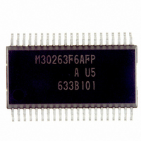
M30263F6AFP#U5A Renesas Electronics America, M30263F6AFP#U5A Datasheet - Page 82

M30263F6AFP#U5A
Manufacturer Part Number
M30263F6AFP#U5A
Description
IC M16C/26A MCU FLASH 42-SSOP
Manufacturer
Renesas Electronics America
Series
M16C™ M16C/Tiny/26r
Datasheet
1.M30260F3AGPU5A.pdf
(354 pages)
Specifications of M30263F6AFP#U5A
Core Processor
M16C/60
Core Size
16-Bit
Speed
20MHz
Connectivity
I²C, IEBus, SIO, UART/USART
Peripherals
DMA, PWM, Voltage Detect, WDT
Number Of I /o
33
Program Memory Size
48KB (48K x 8)
Program Memory Type
FLASH
Ram Size
2K x 8
Voltage - Supply (vcc/vdd)
2.7 V ~ 5.5 V
Data Converters
A/D 10x10b
Oscillator Type
Internal
Operating Temperature
-20°C ~ 85°C
Package / Case
42-SSOP
For Use With
R0K33026AS000BE - KIT DEV EVALUATION M16C/26A
Lead Free Status / RoHS Status
Lead free / RoHS Compliant
Eeprom Size
-
- Current page: 82 of 354
- Download datasheet (4Mb)
R
R
M
e
E
1
. v
J
6
0
9.1.2 Hardware Interrupts
2
C
9
0 .
B
2 /
Hardware interrupts are classified into two types — special interrupts and peripheral function interrupts.
0
0
9.1.2.1 Special Interrupts
9.1.2.2 Peripheral Function Interrupts
6
2
A
Special interrupts are non-maskable interrupts.
9.1.2.1.1 NMI Interrupt
9.1.2.1.2 DBC Interrupt
9.1.2.1.3 Watchdog Timer Interrupt
9.1.2.1.4 Oscillation Stop and Re-oscillation Detection Interrupt
9.1.2.1.5 Voltage Down Detection Interrupt
9.1.2.1.6 Single-step Interrupt
9.1.2.1.7 Address Match Interrupt
Peripheral function interrupts are maskable interrupts and generated by the microcomputer's internal
functions. The interrupt sources for peripheral function interrupts are listed in Table 9.2.2.1
Relocatable Vector Tables. For details about the peripheral functions, refer to the description of
each peripheral function in this manual.
0
F
2
An NMI interrupt is generated when input on the NMI pin changes state from high to low. For details
about the NMI interrupt, refer to the section 9.7 NMI Interrupt.
This interrupt is exclusively for debugger, do not use in any other circumstances.
Generated by the watchdog timer. Once a watchdog timer interrupt is generated, be sure to initialize
the watchdog timer. For details about the watchdog timer, refer to the section 10. Watchdog Timer.
Generated by the oscillation stop and re-oscillation detection function. For details about the oscilla-
tion stop and re-oscillation detection function, refer to the section 7. Clock Generating Circuit.
Generated by the voltage detection circuit. For details about the voltage detection circuit, refer to the
section 5.5 Voltage Detection Circuit.
Do not normally use this interrupt because it is provided exclusively for use by development tools.
An address match interrupt is generated immediately before executing the instruction at the address
indicated by the RMAD0 or RMAD1 register, if the corresponding enable bit (the AIER0 or AIER1 bit
in the AIER register) is set to “1”. For details about the address match interrupt, refer to the section
9.9 Address Match Interrupt.
e
G
0 -
b
1 .
o r
2
_______
0
, 5
u
0
p
2
0
(
_______
________
M
0
7
_______
1
6
C
page 63
2 /
6
, A
M
1
f o
6
C
3
2
2 /
9
6
, B
M
1
6
C
2 /
6
) T
_______
_______
9. Interrupt
Related parts for M30263F6AFP#U5A
Image
Part Number
Description
Manufacturer
Datasheet
Request
R

Part Number:
Description:
KIT STARTER FOR M16C/29
Manufacturer:
Renesas Electronics America
Datasheet:

Part Number:
Description:
KIT STARTER FOR R8C/2D
Manufacturer:
Renesas Electronics America
Datasheet:

Part Number:
Description:
R0K33062P STARTER KIT
Manufacturer:
Renesas Electronics America
Datasheet:

Part Number:
Description:
KIT STARTER FOR R8C/23 E8A
Manufacturer:
Renesas Electronics America
Datasheet:

Part Number:
Description:
KIT STARTER FOR R8C/25
Manufacturer:
Renesas Electronics America
Datasheet:

Part Number:
Description:
KIT STARTER H8S2456 SHARPE DSPLY
Manufacturer:
Renesas Electronics America
Datasheet:

Part Number:
Description:
KIT STARTER FOR R8C38C
Manufacturer:
Renesas Electronics America
Datasheet:

Part Number:
Description:
KIT STARTER FOR R8C35C
Manufacturer:
Renesas Electronics America
Datasheet:

Part Number:
Description:
KIT STARTER FOR R8CL3AC+LCD APPS
Manufacturer:
Renesas Electronics America
Datasheet:

Part Number:
Description:
KIT STARTER FOR RX610
Manufacturer:
Renesas Electronics America
Datasheet:

Part Number:
Description:
KIT STARTER FOR R32C/118
Manufacturer:
Renesas Electronics America
Datasheet:

Part Number:
Description:
KIT DEV RSK-R8C/26-29
Manufacturer:
Renesas Electronics America
Datasheet:

Part Number:
Description:
KIT STARTER FOR SH7124
Manufacturer:
Renesas Electronics America
Datasheet:

Part Number:
Description:
KIT STARTER FOR H8SX/1622
Manufacturer:
Renesas Electronics America
Datasheet:

Part Number:
Description:
KIT DEV FOR SH7203
Manufacturer:
Renesas Electronics America
Datasheet:


