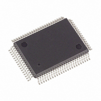
DS5000FP-16+ Maxim Integrated Products, DS5000FP-16+ Datasheet - Page 6

DS5000FP-16+
Manufacturer Part Number
DS5000FP-16+
Description
IC MODULE MICRO 16MHZ 80-QFP
Manufacturer
Maxim Integrated Products
Series
DS500xr
Datasheet
1.DS5000FP-16.pdf
(22 pages)
Specifications of DS5000FP-16+
Core Processor
8051
Core Size
8-Bit
Speed
16MHz
Connectivity
EBI/EMI, SIO, UART/USART
Peripherals
Power-Fail Reset, WDT
Number Of I /o
32
Program Memory Type
SRAM
Ram Size
128 x 8
Voltage - Supply (vcc/vdd)
4.75 V ~ 5.25 V
Oscillator Type
External
Operating Temperature
0°C ~ 70°C
Package / Case
80-MQFP, 80-PQFP
Processor Series
DS5000
Core
8051
Data Bus Width
8 bit
Program Memory Size
8 KB to 64 KB
Data Ram Size
8 KB to 64 KB
Interface Type
3-Wire, RS-232, UART
Maximum Clock Frequency
16 MHz
Number Of Programmable I/os
32
Number Of Timers
2
Operating Supply Voltage
4.75 V to 5.25 V
Maximum Operating Temperature
+ 70 C
Mounting Style
SMD/SMT
Development Tools By Supplier
DS5000TK
Minimum Operating Temperature
0 C
Lead Free Status / RoHS Status
Lead free / RoHS Compliant
Eeprom Size
-
Program Memory Size
-
Data Converters
-
Lead Free Status / Rohs Status
Details
DS5000FP
INSTRUCTION SET
The DS5000FP executes an instruction set that is object code compatible with the industry standard 8051
microcontroller. As a result, software development packages such as assemblers and compilers that have
been written for the 8051 are compatible with the DS5000FP. A complete description of the instruction
set and operation are provided in the Secure Microcontroller User’s Guide.
Also note that the DS5000FP is embodied in the DS5000(T) and DS2250(T) modules. The DS5000(T)
combines the DS5000FP with one SRAM of either 8 or 32 kbytes and a lithium cell. An optional Real
Time Clock is also available in the DS5000T. This is packaged in a 40-pin DIP module. The DS2250(T)
is an identical function in a SIMM form factor. It also offers the option of a second 32k SRAM mapped
as data on Chip Enable 2.
MEMORY ORGANIZATION
Figure 2 illustrates the memory map accessed by the DS5000FP. The entire 64k of program and 64k of
data is available. The DS5000FP maps 32k of this space into the SRAM connected to the byte-wide bus.
This is the area from 0000h to 7FFFh (32k) and is reached via
. Any area not mapped into the NV
CE1
RAM is reached via the Expanded bus on Ports 0 & 2. Selecting
provides another 32k of potential
CE2
data storage. When
is used, no data is available on the ports. The memory map is covered in detail in
CE2
the Secure Microcontroller User’s Guide.
Figure 3 illustrates a typical memory connection for a system using 8k bytes of SRAM. Figure 4 shows a
similar system with 32 kbytes. The byte-wide Address bus connects to the SRAM address lines. The bi-
directional byte-wide data bus connects the data I/O lines of the SRAM.
provides the chip enable
CE1
and R/
is the write enable. An additional RAM could be connected to
, with common connections
W
CE2
for R/
, BA14-0, and BD7-0.
W
6 of 22


