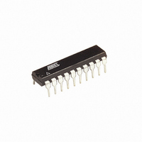
AT90S2313-10PC Atmel, AT90S2313-10PC Datasheet - Page 7

AT90S2313-10PC
Manufacturer Part Number
AT90S2313-10PC
Description
IC MCU 2K FLSH 10MHZ UART 20DIP
Manufacturer
Atmel
Series
AVR® 90Sr
Datasheet
1.AT90S2313-10PC.pdf
(92 pages)
Specifications of AT90S2313-10PC
Core Processor
AVR
Core Size
8-Bit
Speed
10MHz
Connectivity
SPI, UART/USART
Peripherals
Brown-out Detect/Reset, POR, PWM, WDT
Number Of I /o
15
Program Memory Size
2KB (1K x 16)
Program Memory Type
FLASH
Eeprom Size
128 x 8
Ram Size
128 x 8
Voltage - Supply (vcc/vdd)
4 V ~ 6 V
Oscillator Type
External
Operating Temperature
0°C ~ 70°C
Package / Case
20-DIP (0.300", 7.62mm)
Lead Free Status / RoHS Status
Contains lead / RoHS non-compliant
Data Converters
-
Available stocks
Company
Part Number
Manufacturer
Quantity
Price
Company:
Part Number:
AT90S2313-10PC
Manufacturer:
ATM
Quantity:
1 980
Company:
Part Number:
AT90S2313-10PC
Manufacturer:
ATM
Quantity:
1 980
Part Number:
AT90S2313-10PC
Manufacturer:
ATMEL/爱特梅尔
Quantity:
20 000
Part Number:
AT90S2313-10PCS
Manufacturer:
ATMEL/爱特梅尔
Quantity:
20 000
General Purpose
Register File
X-register, Y-register, and Z-
register
0839I–AVR–06/02
Figure 6 shows the structure of the 32 general purpose registers in the CPU.
Figure 6. AVR CPU General Purpose Working Registers
All the register operating instructions in the instruction set have direct and single-cycle
access to all registers. The only exception is the five constant arithmetic and logic
instructions SBCI, SUBI, CPI, ANDI, ORI between a constant and a register and the LDI
instruction for load immediate constant data. These instructions apply to the second half
of the registers in the Register File (R16..R31). The general SBC, SUB, CP, AND, OR,
and all other operations between two registers or on a single register apply to the entire
Register File.
As shown in Figure 6, each register is also assigned a data memory address, mapping
them directly into the first 32 locations of the user Data Space. Although the Register
File is not physically implemented as SRAM locations, this memory organization pro-
vides great flexibility in access of the registers, as the X-, Y-, and Z-registers can be set
to index any register in the file.
The registers R26..R31 have some added functions to their general purpose usage.
These registers are the address pointers for indirect addressing of the Data Space. The
three indirect address registers X, Y and Z are defined in Figure 7.
Figure 7. X-, Y-, and Z-Registers
Y-register
Z-register
X-register
Registers
Purpose
Working
General
15
7
15
7
15
7
R27 ($1B)
R29 ($1D)
R31 ($1F)
7
R13
R14
R15
R16
R17
R26
R27
R28
R29
R30
R31
R0
R1
R2
…
…
0
0
0
0
7
7
7
Addr.
$0D
$0E
$1A
$1B
$1C
$1D
$1E
$00
$01
$02
$0F
$10
$11
$1F
R26 ($1A)
R28 ($1C)
R30 ($1E)
AT90S2313
X-register High Byte
Y-register High Byte
Z-register High Byte
X-register Low Byte
Y-register Low Byte
Z-register Low Byte
0
0
0
0
0
0
7


