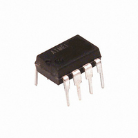
ATTINY13-20PJ Atmel, ATTINY13-20PJ Datasheet - Page 93

ATTINY13-20PJ
Manufacturer Part Number
ATTINY13-20PJ
Description
IC MCU AVR 1K 5V 20MHZ 8DIP
Manufacturer
Atmel
Series
AVR® ATtinyr
Specifications of ATTINY13-20PJ
Core Processor
AVR
Core Size
8-Bit
Speed
20MHz
Peripherals
Brown-out Detect/Reset, POR, PWM, WDT
Number Of I /o
6
Program Memory Size
1KB (512 x 16)
Program Memory Type
FLASH
Eeprom Size
64 x 8
Ram Size
64 x 8
Voltage - Supply (vcc/vdd)
2.7 V ~ 5.5 V
Data Converters
A/D 4x10b
Oscillator Type
Internal
Operating Temperature
-40°C ~ 85°C
Package / Case
8-DIP (0.300", 7.62mm)
Lead Free Status / RoHS Status
Lead free / RoHS Compliant
Connectivity
-
Other names
ATTINY13-24PJ
ATTINY13-24PJ
ATTINY13-24PJ
- Current page: 93 of 176
- Download datasheet (3Mb)
14.12.3
14.12.3.1
14.12.3.2
2535J–AVR–08/10
ADCL and ADCH – The ADC Data Register
ADLAR = 0
ADLAR = 1
• Bit 3 – ADIE: ADC Interrupt Enable
When this bit is written to one and the I-bit in SREG is set, the ADC Conversion Complete Inter-
rupt is activated.
• Bits 2:0 – ADPS2:0: ADC Prescaler Select Bits
These bits determine the division factor between the system clock frequency and the input clock
to the ADC.
Table 14-4.
When an ADC conversion is complete, the result is found in these two registers.
When ADCL is read, the ADC Data Register is not updated until ADCH is read. Consequently, if
the result is left adjusted and no more than 8-bit precision is required, it is sufficient to read
ADCH. Otherwise, ADCL must be read first, then ADCH.
Bit
Read/Write
Initial Value
Bit
Read/Write
Initial Value
ADPS2
0
0
0
0
1
1
1
1
ADC Prescaler Selections
ADC7
ADC9
ADC1
15
15
R
R
R
R
–
7
0
0
7
0
0
ADC6
ADC8
ADC0
14
14
ADPS1
R
R
R
R
–
6
0
0
6
0
0
0
0
1
1
0
0
1
1
ADC5
ADC7
13
13
R
R
R
R
–
5
0
0
–
5
0
0
ADC4
ADC6
12
12
R
R
R
R
–
4
0
0
–
4
0
0
ADPS0
0
1
0
1
0
1
0
1
ADC3
ADC5
11
11
R
R
R
R
–
3
0
0
–
3
0
0
ADC2
ADC4
10
10
R
R
R
R
–
2
0
0
–
2
0
0
ADC9
ADC1
ADC3
Division Factor
R
R
R
R
9
1
0
0
9
–
1
0
0
128
16
32
64
2
2
4
8
ADC8
ADC0
ADC2
8
0
R
R
0
0
8
–
0
R
R
0
0
ADCH
ADCH
ADCL
ADCL
93
Related parts for ATTINY13-20PJ
Image
Part Number
Description
Manufacturer
Datasheet
Request
R

Part Number:
Description:
IC MCU AVR 1K FLASH 20MHZ 8SOIC
Manufacturer:
Atmel
Datasheet:

Part Number:
Description:
Manufacturer:
Atmel Corporation
Datasheet:

Part Number:
Description:
IC MCU AVR 1K FLASH 20MHZ 8SOIC
Manufacturer:
Atmel
Datasheet:

Part Number:
Description:
IC MCU AVR 1K FLASH 10MHZ 20-MLF
Manufacturer:
Atmel
Datasheet:

Part Number:
Description:
IC MCU AVR 1K FLASH 20MHZ 8DIP
Manufacturer:
Atmel
Datasheet:

Part Number:
Description:
MCU AVR 1KB FLASH 20MHZ 3X3 QFN
Manufacturer:
Atmel
Datasheet:

Part Number:
Description:
IC MCU AVR 1K FLASH 20MHZ 8SOIC
Manufacturer:
Atmel
Datasheet:

Part Number:
Description:
IC MCU AVR 1K 5V 20MHZ 8SOIC
Manufacturer:
Atmel
Datasheet:

Part Number:
Description:
IC MCU AVR 1K 5V 20MHZ 8SOIC
Manufacturer:
Atmel
Datasheet:

Part Number:
Description:
IC MCU AVR 1K FLASH 20MHZ 8DIP
Manufacturer:
Atmel
Datasheet:

Part Number:
Description:
IC MCU AVR 1K FLASH 20MHZ 8SOIC
Manufacturer:
Atmel
Datasheet:

Part Number:
Description:
MCU AVR 1KB FLASH 20MHZ 8SOIC GW
Manufacturer:
Atmel
Datasheet:


