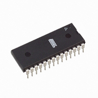
ATMEGA88V-10PU Atmel, ATMEGA88V-10PU Datasheet - Page 278

ATMEGA88V-10PU
Manufacturer Part Number
ATMEGA88V-10PU
Description
IC AVR MCU 8K 10MHZ 1.8V 28DIP
Manufacturer
Atmel
Series
AVR® ATmegar
Datasheets
1.ATAVRTS2080B.pdf
(378 pages)
2.ATMEGA48-20AU.pdf
(35 pages)
3.ATMEGA88V-10PU.pdf
(377 pages)
Specifications of ATMEGA88V-10PU
Core Processor
AVR
Core Size
8-Bit
Speed
10MHz
Connectivity
I²C, SPI, UART/USART
Peripherals
Brown-out Detect/Reset, POR, PWM, WDT
Number Of I /o
23
Program Memory Size
8KB (4K x 16)
Program Memory Type
FLASH
Eeprom Size
512 x 8
Ram Size
1K x 8
Voltage - Supply (vcc/vdd)
1.8 V ~ 5.5 V
Data Converters
A/D 6x10b
Oscillator Type
Internal
Operating Temperature
-40°C ~ 85°C
Package / Case
28-DIP (0.300", 7.62mm)
Processor Series
ATMEGA8x
Core
AVR8
Data Bus Width
8 bit
Data Ram Size
1 KB
Interface Type
2-Wire, SPI, USART, Serial
Maximum Clock Frequency
20 MHz
Number Of Programmable I/os
23
Number Of Timers
3 bit
Operating Supply Voltage
1.8 V to 5.5 V
Maximum Operating Temperature
+ 85 C
Mounting Style
Through Hole
3rd Party Development Tools
EWAVR, EWAVR-BL
Minimum Operating Temperature
- 40 C
On-chip Adc
10 bit, 6 Channel
Cpu Family
ATmega
Device Core
AVR
Device Core Size
8b
Frequency (max)
10MHz
Total Internal Ram Size
1KB
# I/os (max)
23
Number Of Timers - General Purpose
3
Operating Supply Voltage (typ)
2.5/3.3/5V
Operating Supply Voltage (max)
5.5V
Operating Supply Voltage (min)
1.8V
Instruction Set Architecture
RISC
Operating Temp Range
-40C to 85C
Operating Temperature Classification
Industrial
Mounting
Through Hole
Pin Count
28
Package Type
PDIP
For Use With
ATAVRDRAGON - KIT DRAGON 32KB FLASH MEM AVRATAVRISP2 - PROGRAMMER AVR IN SYSTEM
Lead Free Status / RoHS Status
Lead free / RoHS Compliant
Available stocks
Company
Part Number
Manufacturer
Quantity
Price
Part Number:
ATMEGA88V-10PU
Manufacturer:
AT
Quantity:
20 000
- Current page: 278 of 378
- Download datasheet (8Mb)
26.8.11
26.8.12
278
ATmega48/88/168
Programming Time for Flash when Using SPM
Simple Assembly Code Example for a Boot Loader
The calibrated RC Oscillator is used to time Flash accesses.
gramming time for Flash accesses from the CPU.
Table 26-5.
Note:
Flash write (Page Erase, Page Write, and
write Lock bits by SPM)
.equ PAGESIZEB = PAGESIZE*2
.org SMALLBOOTSTART
Write_page:
Wrloop:
;-the routine writes one page of data from RAM to Flash
; the first data location in RAM is pointed to by the Y pointer
; the first data location in Flash is pointed to by the Z-pointer
;-error handling is not included
;-the routine must be placed inside the Boot space
; (at least the Do_spm sub routine). Only code inside NRWW section can
; be read during Self-Programming (Page Erase and Page Write).
;-registers used: r0, r1, temp1 (r16), temp2 (r17), looplo (r24),
; loophi (r25), spmcrval (r20)
; storing and restoring of registers is not included in the routine
; register usage can be optimized at the expense of code size
;-It is assumed that either the interrupt table is moved to the Boot
; loader section or that the interrupts are disabled.
; Page Erase
ldi
call Do_spm
; re-enable the RWW section
ldi
call Do_spm
; transfer data from RAM to Flash page buffer
ldi
ldi
ld
ld
ldi
call Do_spm
adiw ZH:ZL, 2
sbiw loophi:looplo, 2
brne Wrloop
; execute Page Write
subi ZL, low(PAGESIZEB)
sbci ZH, high(PAGESIZEB)
ldi
call Do_spm
; re-enable the RWW section
1. Minimum and maximum programming time is per individual operation.
spmcrval, (1<<PGERS) | (1<<SELFPRGEN)
spmcrval, (1<<RWWSRE) | (1<<SELFPRGEN)
looplo, low(PAGESIZEB)
loophi, high(PAGESIZEB)
r0, Y+
r1, Y+
spmcrval, (1<<SELFPRGEN)
spmcrval, (1<<PGWRT) | (1<<SELFPRGEN)
SPM Programming Time
Symbol
(1)
;PAGESIZEB is page size in BYTES, not words
Min Programming Time
;init loop variable
;not required for PAGESIZEB<=256
;use subi for PAGESIZEB<=256
;restore pointer
;not required for PAGESIZEB<=256
3.7 ms
Table 26-5
Max Programming Time
shows the typical pro-
4.5 ms
2545S–AVR–07/10
Related parts for ATMEGA88V-10PU
Image
Part Number
Description
Manufacturer
Datasheet
Request
R

Part Number:
Description:
IC MCU AVR 8K 5V 10MHZ 32-TQFP
Manufacturer:
Atmel
Datasheet:

Part Number:
Description:
IC AVR MCU 8K 10MHZ 1.8V 32TQFP
Manufacturer:
Atmel
Datasheet:

Part Number:
Description:
IC AVR MCU 8K 10MHZ 1.8V 32-QFN
Manufacturer:
Atmel
Datasheet:

Part Number:
Description:
IC MCU AVR 8K 5V 10MHZ 32-TQFP
Manufacturer:
Atmel
Datasheet:

Part Number:
Description:
IC MCU AVR 8K 5V 10MHZ 32-QFN
Manufacturer:
Atmel
Datasheet:

Part Number:
Description:
IC MCU AVR 8K 5V 10MHZ 32-QFN
Manufacturer:
Atmel
Datasheet:

Part Number:
Description:
IC MCU AVR 8K 5V 10MHZ 28-DIP
Manufacturer:
Atmel
Datasheet:

Part Number:
Description:
IC MCU AVR 8K 5V 10MHZ 28-DIP
Manufacturer:
Atmel
Datasheet:

Part Number:
Description:
MCU AVR 8K FLASH 10MHZ 32TQFP
Manufacturer:
Atmel
Datasheet:

Part Number:
Description:
MCU AVR 8K FLASH 10MHZ 32QFN
Manufacturer:
Atmel
Datasheet:

Part Number:
Description:
IC MCU AVR 8K 5V 20MHZ 32-TQFP
Manufacturer:
Atmel
Datasheet:

Part Number:
Description:
Manufacturer:
Atmel Corporation
Datasheet:


