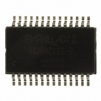
SX28AC/SS-G Parallax Inc, SX28AC/SS-G Datasheet - Page 2

SX28AC/SS-G
Manufacturer Part Number
SX28AC/SS-G
Description
IC RISC MCU 2KX12 EE/FLASH28S
Manufacturer
Parallax Inc
Series
SXr
Datasheet
1.SX20ACSS-G.pdf
(51 pages)
Specifications of SX28AC/SS-G
Core Size
8-Bit
Program Memory Size
3KB (2K x 12)
Oscillator Type
Internal
Core Processor
RISC
Speed
75MHz
Peripherals
Brown-out Detect/Reset, POR, WDT
Number Of I /o
20
Program Memory Type
FLASH
Ram Size
136 x 8
Voltage - Supply (vcc/vdd)
3 V ~ 5.5 V
Operating Temperature
0°C ~ 70°C
Package / Case
28-DIP (0.300", 7.62mm)
Controller Family/series
SX
No. Of I/o's
20
Eeprom Memory Size
2048Byte
Ram Memory Size
136Byte
Cpu Speed
75MHz
Processor Series
Ubicom SXx
Core
RISC
Data Bus Width
8 bit
Data Ram Size
136 B
Maximum Clock Frequency
75 MHz
Number Of Programmable I/os
20
Number Of Timers
1
Operating Supply Voltage
4.5 V to 5.5 V
Maximum Operating Temperature
+ 70 C
Mounting Style
SMD/SMT
Development Tools By Supplier
32300, 45302
Minimum Operating Temperature
0 C
Lead Free Status / RoHS Status
Lead free / RoHS Compliant
Eeprom Size
-
Data Converters
-
Connectivity
-
Lead Free Status / Rohs Status
Details
Available stocks
Company
Part Number
Manufacturer
Quantity
Price
Company:
Part Number:
SX28AC/SS-G
Manufacturer:
UBKOM
Quantity:
5 510
Part Number:
SX28AC/SS-G
Manufacturer:
SCENIX
Quantity:
20 000
Parallax SX20AC/SX28AC
1.0
1.1.
1.2.
1.3.
1.4.
1.5.
1.6.
1.7.
1.8.
2.0
2.1.
2.2.
2.3.
3.0
3.1.
3.2.
4.0
4.1.
4.2.
4.3.
5.0
5.1.
5.2.
5.3.
6.0
6.1.
6.2.
7.0
7.1.
7.2.
8.0
9.0
9.1.
9.2.
9.3.
9.4.
10.0
10.1.
© Parallax Inc.
1.4.1.
3.1.1.
3.2.1.
3.2.2.
3.2.3.
6.1.1.
6.1.2.
6.2.1.
Product Overview......................................................... 1
Introduction ................................................................................1
Key Features..............................................................................3
Architecture................................................................................4
Programming Benefits in Assembly and High-Level Languages 4
Programming and Debugging Support .......................................4
Applications................................................................................4
Support ......................................................................................4
Part Numbering..........................................................................5
Connection Diagrams .................................................. 6
Pin Assignments ........................................................................6
Pin Descriptions .........................................................................6
Typical Connection Diagrams ....................................................7
Port Descriptions ......................................................... 9
Reading and Writing the Ports ...................................................9
Port Configuration ....................................................................11
Special-Function Registers ....................................... 13
PC Register (02h) ....................................................................13
STATUS Register (03h) ...........................................................13
OPTION Register.....................................................................14
Device Configuration Registers................................ 15
FUSE Word (Read/Program at FFFh in Main Memory Map) ....15
FUSEX Word (Read/Program via Programming Command) ....16
DEVICE Word (Hard-Wired Read-Only)...................................16
Memory Organization ................................................ 17
Program Memory .....................................................................17
Data Memory ...........................................................................17
Power Down Mode ..................................................... 19
Multi-Input Wakeup ..................................................................19
Port B MIWU/Interrupt Configuration........................................20
Interrupt Support........................................................ 21
Oscillator Circuits ...................................................... 23
XT, LP or HS modes ................................................................23
75 MHz Operation....................................................................25
External RC Mode....................................................................25
Internal RC Mode.....................................................................25
Real Time Clock (RTCC)/Watchdog Timer............... 26
RTCC.......................................................................................26
Parallax SX/B Basic Compiler ...............................................................4
Read-Modify-Write Considerations......................................................11
MODE Register ...................................................................................11
Port Configuration Registers ...............................................................11
Port Configuration Upon Reset............................................................12
Program Counter.................................................................................17
Subroutine Stack .................................................................................17
File Select Register (04h)....................................................................17
Table of Contents
Page 2 of 51
10.2.
10.3.
11.0
12.0
13.0
14.0
15.0
15.1.
15.2.
15.3.
15.4.
15.5.
15.6.
15.7.
15.8.
15.9.
15.10.
15.11.
15.12.
15.13.
15.14.
15.15.
15.16.
16.0
16.1.
17.0
17.1.
17.2.
17.3.
17.4.
17.5.
18.0
18.1.
18.2.
18.3.
19.0
19.1.
19.2.
19.3.
19.4.
15.10.1.
15.10.2.
15.10.3.
15.10.4.
15.12.1.
15.12.2.
Watchdog Timer ...................................................................... 26
The Prescaler .......................................................................... 26
Comparator .................................................................27
Reset ............................................................................28
Brown-Out Detector ...................................................29
Register States upon Different Reset Operations ...30
Instruction Set ............................................................31
Instruction Set Features........................................................... 31
Instruction Execution ............................................................... 31
Addressing Modes ................................................................... 31
RAM Addressing...................................................................... 32
The Bank Instruction................................................................ 32
Bit Manipulation ....................................................................... 32
Input/Output Operation ............................................................ 32
Increment/Decrement .............................................................. 32
Loop Counting and Data Pointing Testing................................ 32
Branch and Loop Call Instructions ........................................... 32
Return Instructions................................................................... 33
Subroutine Operation............................................................... 33
Comparison and Conditional Branch Instructions .................... 34
Logical Instruction.................................................................... 34
Shift and Rotate Instructions.................................................... 34
Complement and SWAP.......................................................... 34
Native SX Instruction Set Summary Tables .............35
Equivalent Assembler Mnemonics ........................................... 39
Electrical Characteristics...........................................40
Absolute Maximum Ratings ..................................................... 40
DC Characteristics................................................................... 41
AC Characteristics ................................................................... 42
Comparator DC and AC Specifications.................................... 42
Typical Performance Characteristics (25°C) ............................ 43
Package Dimensions..................................................46
SX20AC/SS ............................................................................. 46
SX28AC/SS ............................................................................. 47
SX28AC/DP............................................................................. 48
Manufacturing Information ........................................49
Reflow Peak Temperature ....................................................... 49
MSL3 Compliance ................................................................... 49
Green/RoHS Compliance ........................................................ 49
Stress Testing Data Summary ................................................. 49
Jump Operation .................................................................................. 33
Page Jump Operation......................................................................... 33
Call Operation..................................................................................... 33
Page Call Operation ........................................................................... 33
Push Operation................................................................................... 33
Pop Operation .................................................................................... 34
Rev 1.6 11/20/2006
www.parallax.com


