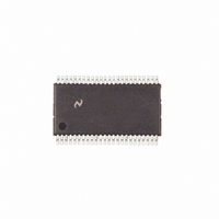
COP8SBR9IMT8 National Semiconductor, COP8SBR9IMT8 Datasheet - Page 30

COP8SBR9IMT8
Manufacturer Part Number
COP8SBR9IMT8
Description
IC MCU EEPROM 8BIT 32K 48-TSSOP
Manufacturer
National Semiconductor
Series
COP8™ 8Sr
Datasheet
1.COP8SCR9HVA8NOPB.pdf
(80 pages)
Specifications of COP8SBR9IMT8
Core Processor
COP8
Core Size
8-Bit
Speed
20MHz
Connectivity
Microwire/Plus (SPI), UART/USART
Peripherals
Brown-out Detect/Reset, POR, PWM, WDT
Number Of I /o
39
Program Memory Size
32KB (32K x 8)
Program Memory Type
FLASH
Ram Size
1K x 8
Voltage - Supply (vcc/vdd)
2.7 V ~ 5.5 V
Oscillator Type
Internal
Operating Temperature
-40°C ~ 85°C
Package / Case
48-TSSOP
Lead Free Status / RoHS Status
Contains lead / RoHS non-compliant
Eeprom Size
-
Data Converters
-
Other names
*COP8SBR9IMT8
www.national.com
PGMTIM_SET
PAGE_ERASE
MASS_ERASE
READ_BYTE
BLOCKR
WRITE_BYTE
BLOCKW
EXIT
INVALID
11.0 In-System Programming
11.6 RETURN TO FLASH MEMORY WITHOUT
HARDWARE RESET
After programming the entire program memory, including
options, it is necessary to exit the Boot ROM and return to
the flash program memory for program execution. Upon
receipt and completion of the EXIT command through the
MICROWIRE/PLUS ISP, the ISP code will reset the part and
begin execution from the flash program memory as de-
scribed in the Reset section. This assumes that the FLEX bit
in the Option register was programmed to 1.
11.7 MICROWIRE/PLUS ISP
National Semiconductor provides a program, which is avail-
able from our web site at www.national.com/cop8, that is
capable of programming a device from the parallel port of a
PC. The software accepts manually input commands and is
capable of downloading standard Intel HEX Format files.
Users who wish to write their own MICROWIRE/PLUS ISP
host software should refer to the COP8 FLASH ISP User
Note: The user must ensure that Block Writes do not cross a 64 byte boundary within one operation.
11.8 USER ISP AND VIRTUAL E
The following commands will support transferring blocks of
data from RAM to flash program memory, and vice-versa.
The user is expected to enforce application security in this
case.
(Continued)
Command
Write Pulse Timing
Register
Page Erase
Mass Erase
Read Byte
Block Read
Write Byte
Block Write
EXIT
N/A
Function
2
TABLE 10. MICROWIRE/PLUS ISP Commands
Value (Hex)
Command
0xBF
0x1D
0xD3
0x3B
0xB3
0xA3
0x8F
0x71
30
Manual, available from the same web site. This document
includes details of command format and delays necessary
between command bytes.
The MICROWIRE/PLUS ISP supports the following features
and commands:
• Write a value to the ISP Write Timing Register. NOTE:
• Erase the entire flash program memory (mass erase).
• Erase a page at a specified address.
• Read Option register.
• Read a byte from a specified address.
• Write a byte to a specified address.
• Read multiple bytes starting at a specified address.
• Write multiple bytes starting at a specified address.
• Exit ISP and return execution to flash program memory.
The following table lists the MICROWIRE/PLUS ISP com-
mands and provides information on required parameters and
return values.
• Erase the entire flash program memory (mass erase).
• Erase a page of flash memory at a specified address.
• Read a byte from a specified address.
• Write a byte to a specified address.
This must be the first command after entering
MICROWIRE/PLUS ISP mode.
NOTE: Execution of this command will force the device
into the MICROWIRE/PLUS ISP mode.
Value
Starting Address of
Page
Confirmation Code
Address High, Address
Low
Address High, Address
Low, Byte Count (n)
High, Byte Count (n)
Low
0 ≤ n ≤ 32767
Address High, Address
Low, Data Byte
Address High, Address
Low, Byte Count (0 ≤ n
≤ 16), n Data Bytes
N/A
Any other invalid
command will be
ignored
Parameters
N/A
N/A
N/A (The entire Flash
Memory will be erased)
Data Byte if Security not
set. 0xFF if Security set.
Option Register if address
= 0xFFFF, regardless of
Security
n Data Bytes if Security
not set.
n Bytes of 0xFF if
Security set.
N/A
N/A
N/A (Device will Reset)
N/A
Return Data


