AP358SG-13 Diodes Inc, AP358SG-13 Datasheet - Page 9
AP358SG-13
Manufacturer Part Number
AP358SG-13
Description
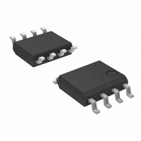
IC OPAMP DUAL LOW POWER 8-SOIC
Manufacturer
Diodes Inc
Datasheet
1.AP358SG-13.pdf
(16 pages)
Specifications of AP358SG-13
Amplifier Type
General Purpose
Number Of Circuits
2
Gain Bandwidth Product
1MHz
Current - Input Bias
45nA
Voltage - Input Offset
2000µV
Current - Supply
1mA
Current - Output / Channel
40mA
Voltage - Supply, Single/dual (±)
3 V ~ 32 V, ±1.5 V ~ 16 V
Operating Temperature
0°C ~ 70°C
Mounting Type
Surface Mount
Package / Case
8-SOIC (3.9mm Width)
Number Of Channels
2
Common Mode Rejection Ratio (min)
65 dB
Input Offset Voltage
7 mV
Input Bias Current (max)
250 nA
Output Current (typ)
40 mA
Operating Supply Voltage
32 V
Supply Current
1.2 mA
Maximum Power Dissipation
600 mW
Maximum Operating Temperature
+ 70 C
Minimum Operating Temperature
0 C
Dual Supply Voltage
+/- 3 V, +/- 5 V, +/- 9 V
Maximum Dual Supply Voltage
+/- 16 V
Minimum Dual Supply Voltage
+/- 1.5 V
Mounting Style
SMD/SMT
Shutdown
No
Supply Voltage (max)
32 V
Supply Voltage (min)
3 V
Voltage Gain Db
100 dB
Lead Free Status / RoHS Status
Lead free / RoHS Compliant
Output Type
-
-3db Bandwidth
-
Slew Rate
-
Lead Free Status / Rohs Status
Lead free / RoHS Compliant
Other names
AP358SGDITR
Available stocks
Company
Part Number
Manufacturer
Quantity
Price
Company:

Part Number:
AP358SG-13
Manufacturer:
DIODES
Quantity:
1 625
Part Number:
AP358SG-13
Manufacturer:
DIODES/美台
Quantity:
20 000
Company:
Part Number:
AP358SG-13-89
Manufacturer:
DIODES
Quantity:
2 869


Electrical Characteristics
Notes:
AP358
Document number: DS31007 Rev. 6 - 2
Symbol
CMRR
PSRR
V
V
A
I
I
I
ICM
IO
B
S
IO
V
5. The AP358 temperature specifications are limited to 0°C < T
6. V
7. The direction of the input current is out of the IC due to the PNP input stage. This current is essentially constant, independent of
8. The input common-mode voltage of either input signal voltage should not be allowed to go negative by more than 0.3V (at25°C).
9. Due to proximity of external components, insure that coupling is not originating via stray capacitance between these
external parts. This typically can be detected as this type of capacitance increases at higher frequencies.
the state of the output so no loading change exists on the input lines.
The upper end of the common-mode voltage range is V
damage, independent of the magnitude of V
O
≅ 1.4V, R
Input Offset Voltage
Input Bias Current
Input Offset Current
Input Common-Mode Voltage Range
Supply Current
Over Full Temperature Range
Large Signal Voltage Gain
Common-Mode Rejection Ratio
Power Supply Rejection Ratio
Amplifier-to-Amplifier Coupling
S
= 0Ω with V
Parameter
+
from 5V to 30V; and over the full input common-mode range (0V to V
(T
A
= 25
o
C, V
+
.
+
= +5.0V, unless otherwise stated) (Note 5)
www.diodes.com
LOW POWER DUAL OPERATIONAL AMPLIFIERS
T
I
V
I
V
T
R
All Op
Amps
V
R
(For V
T
V
V
T
f = 1KHz to 20 KHz,
T
(Input Referred),
(Note 9)
IN(+)
IN(+)
T
+
9 of 16
A
A
A
A
A
CM
+
+
+
+
L
L
-1.5V (at 25°C), but either or both inputs can go to +32V without
A
= 25
= 30V, (Note 8)
= 25°C
= ∞ on
= 15V, T
= 25°C, V
-1.5V
= 5V to 30V,
= 25°C
= 25°C
> 2kΩ,
= 25°C
= 0V, (Note 7)
or I
- I
A
< +70°C.
Conditions
O
IN(−)
o
IN(−)
= 1V to 11V)
C, (Note 6)
,V
, T
A
CM
V
V
CM
= 25°C,
A
+
+
= 0V,
= 25°C,
= 30V
= 5V
= 0V to
Min
25
65
65
0
-
-
-
-
-
-
+
Typ.
-120
100
100
0.5
-1.5V) at 25°C.
45
85
2
5
1
-
V
Max
250
+
1.2
50
7
2
-1.5
© Diodes Incorporated
-
-
-
-
AP358
July 2010
V/mV
Unit
mV
mA
nA
nA
dB
dB
dB
V
Related parts for AP358SG-13
Image
Part Number
Description
Manufacturer
Datasheet
Request
R

Part Number:
Description:
IC OPERATIONAL AMP DUAL 8-SOIC
Manufacturer:
Diodes Inc
Datasheet:

Part Number:
Description:
Diodes (General Purpose, Power, Switching) 240V 350mW
Manufacturer:
Diodes Inc
Datasheet:

Part Number:
Description:
Diodes (General Purpose, Power, Switching) -
Manufacturer:
Diodes Inc
Part Number:
Description:
Diodes (General Purpose, Power, Switching) -
Manufacturer:
Diodes Inc

Part Number:
Description:
Diodes (General Purpose, Power, Switching) NPN Small SIG 50V 45V VCEO 6.0V VEBO
Manufacturer:
Diodes Inc
Datasheet:
Part Number:
Description:
Diodes (General Purpose, Power, Switching) NPN Small SIG 30V 30V VCEO 5.0V VEBO
Manufacturer:
Diodes Inc
Datasheet:
Part Number:
Description:
Diodes (General Purpose, Power, Switching) NPN Small SIG -80V -65V VCEO -5.0 VEBO
Manufacturer:
Diodes Inc
Datasheet:
Part Number:
Description:
Diodes (General Purpose, Power, Switching) NPN Small SIG -50V -45V VCEO 6.0V VEBO
Manufacturer:
Diodes Inc
Part Number:
Description:
Diodes (General Purpose, Power, Switching) Dual Switching DIODE 100V Vrm 75Vrrm 53Vr
Manufacturer:
Diodes Inc
Datasheet:

Part Number:
Description:
Diodes (General Purpose, Power, Switching) Vr/80V Io/125mA T/R
Manufacturer:
Diodes Inc
Datasheet:

Part Number:
Description:
Diodes (General Purpose, Power, Switching) HV DUAL SW DIODE 300V
Manufacturer:
Diodes Inc
Datasheet:

Part Number:
Description:
Diodes (General Purpose, Power, Switching) 80V 150mW
Manufacturer:
Diodes Inc
Datasheet:
Part Number:
Description:
Diodes (General Purpose, Power, Switching) 75V 150mW
Manufacturer:
Diodes Inc
Datasheet:

Part Number:
Description:
Diodes (General Purpose, Power, Switching) 200MW 80V
Manufacturer:
Diodes Inc
Part Number:
Description:
Diodes (General Purpose, Power, Switching) 100V Io/150mA T/R INVALID P/N
Manufacturer:
Diodes Inc