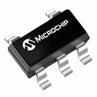
MCP601T-I/OT Microchip Technology, MCP601T-I/OT Datasheet - Page 3

MCP601T-I/OT
Manufacturer Part Number
MCP601T-I/OT
Description
IC OPAMP SNGL SUPPLY R-R SOT23-5
Manufacturer
Microchip Technology
Specifications of MCP601T-I/OT
Slew Rate
2.3 V/µs
Package / Case
SOT-23-5, SC-74A, SOT-25
Amplifier Type
General Purpose
Number Of Circuits
1
Output Type
Rail-to-Rail
Gain Bandwidth Product
2.8MHz
Current - Input Bias
1pA
Voltage - Input Offset
700µV
Current - Supply
230µA
Current - Output / Channel
22mA
Voltage - Supply, Single/dual (±)
2.7 V ~ 6 V
Operating Temperature
-40°C ~ 85°C
Mounting Type
Surface Mount
Number Of Channels
1
Common Mode Rejection Ratio (min)
75 dB
Input Offset Voltage
2 mV
Input Bias Current (max)
60 pA
Operating Supply Voltage
3 V, 5 V
Maximum Operating Temperature
+ 85 C
Minimum Operating Temperature
- 40 C
Mounting Style
SMD/SMT
Shutdown
No
Supply Voltage (max)
6 V
Supply Voltage (min)
2.7 V
Technology
CMOS
Voltage Gain Db
115 dB
Lead Free Status / RoHS Status
Lead free / RoHS Compliant
-3db Bandwidth
-
Lead Free Status / Rohs Status
Lead free / RoHS Compliant
Other names
MCP601T-I/OTTR
MCP601TI/OT
MCP601TI/OT
Available stocks
Company
Part Number
Manufacturer
Quantity
Price
Company:
Part Number:
MCP601T-I/OT
Manufacturer:
VISHAY
Quantity:
46 000
Company:
Part Number:
MCP601T-I/OT
Manufacturer:
MICROCHI
Quantity:
9 965
Part Number:
MCP601T-I/OT
Manufacturer:
MICROCHIP/微芯
Quantity:
20 000
AC CHARACTERISTICS
MCP603 CHIP SELECT (CS) CHARACTERISTICS
FIGURE 1-1:
Timing Diagram.
© 2007 Microchip Technology Inc.
Electrical Specifications: Unless otherwise indicated, T
V
Frequency Response
Gain Bandwidth Product
Phase Margin
Step Response
Slew Rate
Settling Time (0.01%)
Noise
Input Noise Voltage
Input Noise Voltage Density
Input Noise Current Density
Electrical Specifications: Unless otherwise indicated, T
V
CS Low Specifications
CS Logic Threshold, Low
CS Input Current, Low
CS High Specifications
CS Logic Threshold, High
CS Input Current, High
Shutdown V
Amplifier Output Leakage in Shutdown
Timing
CS Low to Amplifier Output Turn-on Time
CS High to Amplifier Output High-Z Time
Hysteresis
Current
OUT
OUT
V
OUT
I
CS
I
CS
≈ V
≈ V
DD
SS
DD
DD
/2, V
/2, V
SS
Parameters
Parameters
current
L
L
(typical)
-700 nA
(typical)
(typical)
700 nA
= V
= V
2 nA
Hi-Z
DD
DD
/2, and R
/2, and R
MCP603 Chip Select (CS)
t
ON
Output Active
L
L
= 100 kΩ to V
= 100 kΩ to V
(typical)
-230 µA
(typical)
(typical)
230 µA
2 nA
GBWP
Sym
t
settle
PM
SR
E
e
e
i
ni
I
I
ni
ni
ni
Q_SHDN
O_SHDN
V
Sym
I
I
t
V
t
HYST
V
CSH
OFF
CSL
t
ON
OFF
IH
IL
L
L
, C
, C
L
L
Hi-Z
Min
—
—
—
—
—
—
—
—
= 50 pF, and CS is tied low. (Refer to
= 50 pF, and CS is tied low. (Refer to
0.8 V
A
A
V
-1.0
-2.0
Min
—
—
—
—
—
= +25°C, V
= +25°C, V
SS
DD
Typ
2.8
2.3
4.5
0.6
50
29
21
7
-0.7
100
Typ
0.7
3.1
0.4
—
—
—
1
DD
DD
= +2.7V to +5.5V, V
= +2.7V to +5.5V, V
Max
—
—
—
—
—
—
—
—
0.2 V
V
Max
2.0
10
—
—
—
—
—
DD
DD
nV/√Hz f = 1 kHz
nV/√Hz f = 10 kHz
fA/√Hz f = 1 kHz
MCP601/1R/2/3/4
Units
µV
MHz
V/µs
µs
°
P-P
Units
µA
µA
µA
nA
µs
ns
V
V
V
G = +1 V/V
G = +1 V/V
G = +1 V/V, 3.8V step
f = 0.1 Hz to 10 Hz
Figure 1-2
Figure 1-2
SS
SS
CS = 0.2V
CS = V
CS = V
CS ≤ 0.2V
CS ≥ 0.8V
V
DD
= GND, V
= GND, V
= 5.0V
DD
DD
and
and
DD
DD
DD
Conditions
CM
CM
Conditions
, G = +1 V/V
, G = +1 V/V, No load.
Figure
Figure
= V
= V
DD
DD
DS21314G-page 3
1-3).
1-3).
/2,
/2,


