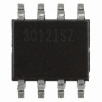
CS3012-ISZ Cirrus Logic Inc, CS3012-ISZ Datasheet - Page 12

CS3012-ISZ
Manufacturer Part Number
CS3012-ISZ
Description
IC OPAMP DUAL PREC LV 8-SOIC
Manufacturer
Cirrus Logic Inc
Datasheet
1.CS3011-ISZ.pdf
(18 pages)
Specifications of CS3012-ISZ
Slew Rate
2 V/µs
Package / Case
8-SOIC
Amplifier Type
Instrumentation
Number Of Circuits
2
Output Type
Rail-to-Rail
Current - Input Bias
50pA
Voltage - Input Offset
10µV
Current - Supply
1.7mA
Voltage - Supply, Single/dual (±)
2.7 V ~ 6.7 V, ±1.35 V ~ 3.35 V
Operating Temperature
-40°C ~ 85°C
Mounting Type
Surface Mount
Number Of Channels
2
Common Mode Rejection Ratio (min)
115 dB
Input Offset Voltage
0.01 mV
Input Bias Current (max)
50 pA
Operating Supply Voltage
2.7 V to 6.7 V
Supply Current
1.7 mA
Maximum Operating Temperature
+ 85 C
Minimum Operating Temperature
- 40 C
Dual Supply Voltage
+/- 3 V
Maximum Dual Supply Voltage
+/- 3.35 V
Minimum Dual Supply Voltage
+/- 1.35 V
Mounting Style
SMD/SMT
Shutdown
No
Supply Voltage (max)
6.7 V
Supply Voltage (min)
2.7 V
Voltage Gain Db
300 dB
Lead Free Status / RoHS Status
Lead free / RoHS Compliant
For Use With
598-1495 - BOARD EVAL OPAMP FOR CS30XX
Current - Output / Channel
-
-3db Bandwidth
-
Gain Bandwidth Product
-
Lead Free Status / Rohs Status
Lead free / RoHS Compliant
Other names
598-1143-5
Available stocks
Company
Part Number
Manufacturer
Quantity
Price
Company:
Part Number:
CS3012-ISZ
Manufacturer:
Cirrus
Quantity:
1 558
The loop gain plot shown in
the unity gain configuration, and indicates how this
is mo dified when using the amplifier in a hig her
gain configuration with compensation. If it is config-
ured for higher gain, for example, 60 dB, the x– axis
will move up by 60 dB (line B). Capacitor C2 adds
a zero and a pole. The modified plot indicates the
effects of introducing the pole and zero due to ca-
pacitor C2 . The pole can be located at any fre-
quency higher than the hand-over frequency, the
zero has to be at a frequency lower than the hand-
over freque ncy so as to provide ade quate ga in
12
Figure 17. Loop Gain Plot: Unity Gain and with Pole-Zero Compensation
Figure 17
i llustrates
-20 dB/dec
FREQUENCY
-100 dB/dec
25 kHz
50kHz
X
margin. The separation between the pole and the
zero is governed by the closed loop gain. The zero
(z
cade and –80 dB/decade slopes. The point X in the
figure should be at closed loop gain plus 20 dB
gain margin. The value for C2 = 1/(2πR1p1). Us-
ing p1 = 500 kHz works very well and is indepen-
dent of ga in. As the closed loop ga in is change d,
the zero location is also modified if R1 remains
fixed. Cap acitor C2 ca n be incre ased in value to
limit the amplifier’s rising noise above 1 kHz.
z
Margin
500 kHz
1
1
-80 dB/dec
) occurs at the intersection o f the –100 dB/de-
1MHz
2.4 MHz
Desired Closed
5MHz
Loop Gain
p
1
B
CS3012
CS3011
DS597F6


