LMH6639MF/NOPB National Semiconductor, LMH6639MF/NOPB Datasheet - Page 6
LMH6639MF/NOPB
Manufacturer Part Number
LMH6639MF/NOPB
Description
IC AMP 190MHZ R-R OTPT SOT23-6
Manufacturer
National Semiconductor
Series
VIP10™r
Datasheet
1.LMH6639MFNOPB.pdf
(20 pages)
Specifications of LMH6639MF/NOPB
Amplifier Type
Voltage Feedback
Number Of Circuits
1
Output Type
Rail-to-Rail
Slew Rate
200 V/µs
Gain Bandwidth Product
90MHz
-3db Bandwidth
228MHz
Current - Input Bias
1.4µA
Voltage - Input Offset
1030µV
Current - Supply
4.18mA
Current - Output / Channel
112mA
Voltage - Supply, Single/dual (±)
3 V ~ 12 V, ±1.5 V ~ 6 V
Operating Temperature
-40°C ~ 85°C
Mounting Type
Surface Mount
Package / Case
SOT-23-6
Number Of Channels
1
Voltage Gain Db
100 dB
Common Mode Rejection Ratio (min)
72 dB
Input Voltage Range (max)
12 V
Input Voltage Range (min)
3 V
Input Offset Voltage
5 mV
Operating Supply Voltage
5 V, 9 V
Supply Current
3.6 mA
Maximum Operating Temperature
+ 85 C
Mounting Style
SMD/SMT
Maximum Dual Supply Voltage
+/- 6 V
Minimum Operating Temperature
- 40 C
Lead Free Status / RoHS Status
Lead free / RoHS Compliant
Other names
LMH6639MF
LMH6639MFTR
LMH6639MFTR
Available stocks
Company
Part Number
Manufacturer
Quantity
Price


www.national.com
I
I
PSRR
I
TH_SD
I_SD PIN
T
T
R
SC
OUT
S
Symbol
ON
OFF
OUT
Note 1: Absolute Maximum Ratings indicate limits beyond which damage to the device may occur. Operating Ratings indicate conditions for which the device is
intended to be functional, but specific performance is not guaranteed. For guaranteed specifications and the test conditions, see the Electrical Characteristics.
Note 2: Human body model, 1.5kΩ in series with 100pF.
Note 3: Applies to both single-supply and split-supply operation. Continuous short circuit operation at elevated ambient temperature can result in exceeding the
maximum allowed junction temperature of 150°C.
Note 4: The maximum power dissipation is a function of T
P
Note 5: Typical values represent the most likely parametric norm.
Note 6: All limits are guaranteed by testing or statistical analysis.
Note 7: Positive current corresponds to current flowing into the device.
Note 8: Slew rate is the average of the rising and falling slew rates.
Note 9: Machine Model, 0Ω in series with 200pF.
Note 10: Short circuit test is a momentary test.
Note 11: Offset voltage average drift determined by dividing the change in V
Note 12: f
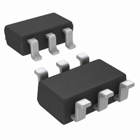
Connection Diagrams
D
= (T
J(MAX)
≤
Output Short Circuit Current
Output Current
Power Supply Rejection Ratio
Supply Current (Enabled)
Supply Current (Disabled)
Threshold Voltage for Shutdown
Mode
Shutdown Pin Input Current
On Time after Shutdown
Off Time to Shutdown
Output Resistance Closed Loop R
- T
1kHz (see typical performance Characteristics)
A
)/ θ
JA
. All numbers apply for packages soldered directly onto a PC board.
Parameter
Top View
SOT23-6
Sourcing to Ground,
Sinking to Ground,
V
(Note
No Load
SD Pin Connected to −5V
R
O
F
F
= 10kΩ, f = 1kHz, A
= 10kΩ, f = 1MHz, A
= 0.5V from either supply
J(MAX)
12)
20030201
, θ
JA
, and T
Conditions
A
. The maximum allowable power dissipation at any ambient temperature is
OS
(Note
6
(Note
at temperature extremes into the total temperature change.
V
V
= −1
= −1
10)
(Note
10)
7)
(Note
Min
100
110
80
85
72
6)
Top View
SOIC-8
V
(Note
+
0.758
4.18
Typ
168
190
112
−84
160
226
− 1.67
96
83
32
5)
(Note
Max
6.5
8.5
1.0
1.3
6)
20030202
Units
nsec
nsec
mΩ
mA
mA
mA
dB
μA
V
Related parts for LMH6639MF/NOPB
Image
Part Number
Description
Manufacturer
Datasheet
Request
R

Part Number:
Description:
190MHz Rail-to-Rail Output Amplifier with Disable
Manufacturer:
National Semiconductor
Datasheet:
Part Number:
Description:
National Semiconductor [8-Bit D/A Converter]
Manufacturer:
National Semiconductor
Datasheet:
Part Number:
Description:
National Semiconductor [Media Coprocessor]
Manufacturer:
National Semiconductor
Datasheet:
Part Number:
Description:
Digitally Controlled Tone and Volume Circuit with Stereo Audio Power Amplifier, Microphone Preamp Stage and National 3D Sound
Manufacturer:
National Semiconductor
Datasheet:
Part Number:
Description:
Digitally Controlled Tone and Volume Circuit with Stereo Audio Power Amplifier, Microphone Preamp Stage and National 3D Sound
Manufacturer:
National Semiconductor
Datasheet:
Part Number:
Description:
AC97 Rev 2 Codec with Sample Rate Conversion and National 3D Sound
Manufacturer:
National Semiconductor
Part Number:
Description:
Manufacturer:
National Semiconductor
Datasheet:
Part Number:
Description:
Manufacturer:
National Semiconductor
Datasheet:
Part Number:
Description:
General Purpose, Low Voltage, Low Power, Rail-to-Rail Output Operational Amplifiers
Manufacturer:
National Semiconductor
Datasheet:
Part Number:
Description:
8-bit 20 MSPS flash A/D converter.
Manufacturer:
National Semiconductor
Datasheet:
Part Number:
Description:
Low Noise Quad Operational Amplifier
Manufacturer:
National Semiconductor
Datasheet:
Part Number:
Description:
Quad Differential Line Receivers
Manufacturer:
National Semiconductor
Datasheet:
Part Number:
Description:
Quad High Speed Trapezoidal? Bus Transceiver
Manufacturer:
National Semiconductor
Datasheet:
Part Number:
Description:
Dual Line Receiver
Manufacturer:
National Semiconductor
Datasheet: