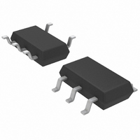
LT1880IS5#TRM Linear Technology, LT1880IS5#TRM Datasheet - Page 9

LT1880IS5#TRM
Manufacturer Part Number
LT1880IS5#TRM
Description
IC OPAMP PICO/IN RR/OUT TSOT23-5
Manufacturer
Linear Technology
Datasheet
1.LT1880CS5TRM.pdf
(12 pages)
Specifications of LT1880IS5#TRM
Amplifier Type
General Purpose
Number Of Circuits
1
Output Type
Rail-to-Rail
Slew Rate
0.55 V/µs
Gain Bandwidth Product
1.1MHz
Current - Input Bias
150pA
Voltage - Input Offset
40µV
Current - Supply
1.5mA
Current - Output / Channel
25mA
Voltage - Supply, Single/dual (±)
2.7 V ~ 36 V, ±1.35 V ~ 18 V
Operating Temperature
-40°C ~ 85°C
Mounting Type
Surface Mount
Package / Case
TSOT-23-5, TSOT-5, TSOP-5
Lead Free Status / RoHS Status
Contains lead / RoHS non-compliant
-3db Bandwidth
-
Other names
LT1880IS5#TRMTR
Available stocks
Company
Part Number
Manufacturer
Quantity
Price
APPLICATIONS INFORMATION
The circuit of Figure 2 shows an extreme example of the
inverting case. The input voltage at the 1M resistor can
swing ±13.5V and the LT1880 will output an inverted,
divided-by-ten version of the input voltage. The input
accuracy is limited by the resistors to 0.2%. Output
referred, this error becomes 2.7mV. The 40μV input offset
voltage contribution, plus the additional error due to input
bias current times the ~100k effective source impedance,
contribute only negligibly to error.
Figure 2. Extreme Inverting Case: Circuit Operates Properly with
Input Voltage Swing Well Outside Op Amp Supply Rails.
±13.5V SWINGS
WELL OUTSIDE
SUPPLY RAILS
V
IN
V
V
REF
IN
1M, 0.1%
INVERTING: A
OP AMP INPUTS DO NOT MOVE,
BUT ARE FIXED AT DC BIAS
POINT V
INPUT DOES NOT HAVE TO BE
RAIL-TO-RAIL
R
G
REF
100k, 0.1%
+
–
V
= –R
LT1880
+
–
–1.5V
1.5V
F
/R
Figure 1. Some Op Amp Confi gurations Do Not Require
Rail-to Rail Inputs to Achieve Rail-to-Rail Outputs
G
R
F
±1.35V
OUTPUT
SWING
1880 F02
V
IN
NONINVERTING: A
INPUTS MOVE BY AS MUCH AS
V
MORE
INPUT MAY NOT HAVE TO BE
RAIL-TO-RAIL
V
IN
REF
, BUT THE OUTPUT MOVES
R
G
+
–
Precision Photodiode Amplifier
Photodiode amplifiers usually employ JFET op amps be-
cause of their low bias current; however, when precision
is required, JFET op amps are generally inadequate due to
their relatively high input offset voltage and drift. The
LT1880 provides a high degree of precision with very low
bias current (I
cable to this demanding task. Figure 3 shows an LT1880
configured as a transimpedance photodiode amplifier.
R
V
F
= 1 +R
F
/R
WORST-CASE
OUTPUT OFFSET
≤196μV AT 25°C
≤262μV 0°C TO 70°C
≤323μV –40°C TO 85°C
PHOTODIODE
G
(SEE TEXT)
Figure 3. Precision Photodiode Amplifi er
B
V
IN
= 150pA typical) and is therefore appli-
NONINVERTING: A
INPUTS MOVE AS MUCH AS
OUTPUT
INPUT MUST BE
RAIL-TO-RAIL FOR OVERALL
CIRCUIT RAIL-TO-RAIL
PERFORMANCE
C
D
+
–
–
+
R
LT1880
F
V
51.1k
C
= +1
–5V
F
5V
1880 F01
LT1880
OUT
1880 F02
1880fa
9


