TC7650IJD Microchip Technology, TC7650IJD Datasheet - Page 4
TC7650IJD
Manufacturer Part Number
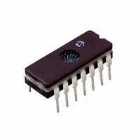
TC7650IJD
Description
IC OPAMP CHOPPER STAB 14CDIP
Manufacturer
Microchip Technology
Datasheet
1.TC7650IJA.pdf
(14 pages)
Specifications of TC7650IJD
Amplifier Type
Chopper (Zero-Drift)
Number Of Circuits
1
Slew Rate
2.5 V/µs
Gain Bandwidth Product
2MHz
Current - Input Bias
1.5pA
Voltage - Input Offset
0.7µV
Current - Supply
2mA
Voltage - Supply, Single/dual (±)
4.5 V ~ 16 V, ±2.25 V ~ 8 V
Operating Temperature
-25°C ~ 85°C
Mounting Type
Through Hole
Package / Case
14-CDIP (0.300", 7.62mm)
Lead Free Status / RoHS Status
Lead free / RoHS Compliant
Output Type
-
Current - Output / Channel
-
-3db Bandwidth
-


TC7650
2.0
The descriptions of the pins are listed in Table 2-1.
TABLE 2-1:
3.0
3.1
Figure 3-1 shows the major elements of the TC7650.
There are two amplifiers (the main amplifier and the
nulling amplifier), and both have offset null capability.
The main amplifier is connected full-time from the input
to the output. The nulling amplifier, under the control of
the chopping frequency oscillator and clock circuit,
alternately nulls itself and the main amplifier. Two exter-
nal capacitors provide the required storage of the null-
ing potentials and the necessary nulling loop time
constants. The nulling arrangement operates over the
full common mode and power supply ranges, and is
also independent of the output level, thus giving excep-
tionally high CMRR, PSRR and A
Careful balancing of the input switches minimizes
chopper frequency charge injection at the input termi-
nals, and the feed forward type injection into the com-
pensation capacitor that can cause output spikes in this
type of circuit.
The circuit's offset voltage compensation is easily
shown. With the nulling inputs shorted, a voltage
almost identical to the nulling amplifier offset voltage is
stored on C
amplifier input is:
EQUATION 3-1:
DS21463B-page 4
8-pin DIP
V OSE
1,8
—
—
—
—
—
2
3
4
5
6
7
Pin Number
PIN DESCRIPTIONS
DETAILED DESCRIPTION
Theory of Operation
=
A
----------------- - V OSN
A N
. The effective offset voltage at the null
14-pin DIP
1
+
1
2,1
3,6
PIN FUNCTION TABLE
10
12
13
14
11
4
5
7
9
8
INT CLK OUT Internal Clock Output
EXT CLK IN
OUTPUT
OUTPUT
INT/EXT
Symbol
+INPUT
-INPUT
CLAMP
C
C
V
V
A
NC
RETN
VOL
, C
DD
SS
B
.
Nulling capacitor pins
Inverting Input
Non-inverting Input
Negative Power Supply
Output Voltage Clamp
Output
Positive Power Supply
No internal connection
Capacitor current return pin
External Clock Input
Select Internal or External Clock
After the nulling amplifier is zeroed, the main amplifier
is zeroed; the A switches open and B switches close.
The output voltage equation is:
EQUATION 3-2:
EQUATION 3-3:
As desired, the device offset voltages are reduced by
the high open loop gain of the nulling amplifier.
3.2
The output circuit is a high impedance stage (approxi-
mately 18kΩ). With loads less than this, the chopper
amplifier behaves in some ways like a trans-conduc-
tance amplifier whose open-loop gain is proportional to
load resistance. For example, the open loop gain will
be 17dB lower with a 1kΩ load than with a 10kΩ load.
If the amplifier is used strictly for DC, the lower gain is
of little consequence, since the DC gain is typically
greater than 120dB, even with a 1kΩ load. In wideband
applications, the best frequency response will be
achieved with a load resistor of 10kΩ or higher. This
results in a smooth 6dB/octave response from 0.1Hz to
2MHz, with phase shifts of less than 10° in the transi-
V
OUT
V OUT
= A
Output Stage/Loading
Description
M
[V
=
OSM
A M A N V
+ (V
(
+
+
©
- V
–
2002 Microchip Technology Inc.
V
-
) + A
-
)
+
V
------------------------------------------ -
N
OSM
(V
+
A
+
- V
N
V
OSN
-
) + A
N
V
OSE
]
Related parts for TC7650IJD
Image
Part Number
Description
Manufacturer
Datasheet
Request
R

Part Number:
Description:
Chopper Stabilized Operational Amplifier
Manufacturer:
Microchip Technology Inc.
Datasheet:
Part Number:
Description:
Manufacturer:
Microchip Technology Inc.
Datasheet:
Part Number:
Description:
Manufacturer:
Microchip Technology Inc.
Datasheet:
Part Number:
Description:
Manufacturer:
Microchip Technology Inc.
Datasheet:
Part Number:
Description:
Manufacturer:
Microchip Technology Inc.
Datasheet:
Part Number:
Description:
Manufacturer:
Microchip Technology Inc.
Datasheet:
Part Number:
Description:
Manufacturer:
Microchip Technology Inc.
Datasheet:
Part Number:
Description:
Manufacturer:
Microchip Technology Inc.
Datasheet:
Part Number:
Description:
Manufacturer:
Microchip Technology Inc.
Datasheet: