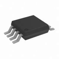
ADA4891-2ARMZ Analog Devices Inc, ADA4891-2ARMZ Datasheet - Page 14

ADA4891-2ARMZ
Manufacturer Part Number
ADA4891-2ARMZ
Description
IC OPAMP GP R-R CMOS DUAL 8MSOP
Manufacturer
Analog Devices Inc
Datasheet
1.ADA4891-2ARMZ.pdf
(20 pages)
Specifications of ADA4891-2ARMZ
Slew Rate
210 V/µs
Amplifier Type
General Purpose
Number Of Circuits
2
Output Type
Rail-to-Rail
-3db Bandwidth
240MHz
Current - Input Bias
2pA
Voltage - Input Offset
2500µV
Current - Supply
4.4mA
Current - Output / Channel
150mA
Voltage - Supply, Single/dual (±)
2.7 V ~ 5.5 V, ±1.35 V ~ 2.75 V
Operating Temperature
-40°C ~ 125°C
Mounting Type
Surface Mount
Package / Case
8-MSOP, Micro8™, 8-uMAX, 8-uSOP,
Op Amp Type
High Speed
No. Of Amplifiers
2
Bandwidth
240MHz
Supply Voltage Range
2.7V To 5.5V
Amplifier Case Style
SO
No. Of Pins
8
Operating Temperature Range
-40°C To +125°C
Lead Free Status / RoHS Status
Lead free / RoHS Compliant
Gain Bandwidth Product
-
Lead Free Status / RoHS Status
Lead free / RoHS Compliant, Lead free / RoHS Compliant
Available stocks
Company
Part Number
Manufacturer
Quantity
Price
Part Number:
ADA4891-2ARMZ
Manufacturer:
ADI/亚德诺
Quantity:
20 000
ADA4891-1/ADA4891-2
DRIVING CAPACITIVE LOADS
A highly capacitive load reacts with the output impedance of
the amplifiers, causing a loss of phase margin and subsequent
peaking or even oscillation, as is shown in Figure 45 and
Figure 46. Four methods that minimize the output capacitive
loading effect include:
•
•
•
•
Reducing the output resistive load. This pushes the pole
further away and, hence, improves the phase margin.
Increase the phase margin with higher noise gains. As
the closed-loop gain is increased, the larger phase margin
allows for large capacitor loads with less peaking.
Adding a parallel capacitor, C
output. This adds a zero in the closed-loop frequency
response, which tends to cancel out the pole formed by
the capacitive load and output impedance of the amplifier.
Refer to the Effect of R
more details.
Putting a small value resistor, R
to isolate the load capacitor from the output stage of
the amplifier.
–100
–10
100
–2
–4
–6
–8
8
6
4
2
0
0
0.1
Figure 45. Closed-Loop Frequency Response, C
V
V
G = +1
R
C
50mV/DIV
S
OUT
L
L
= 5V
= 1kΩ
= 6.8pF
Figure 46. 200 mV Step Response, C
= 200mV p-p
C1
1
FREQUENCY (MHz)
F
on 0.1 dB Gain Flatness section for
F
10
with R
S
, in series with the output
F
, from −IN to the
L
= 6.8 pF
100
L
V
G = +1
R
C
= 6.8 pF
S
L
L
50ns/DIV
= 5V
= 1kΩ
= 6.8pF
Rev. A | Page 14 of 20
Figure 47 shows the effect of using a snub resistor (R
the peaking in the worst-case frequency response (gain of +1).
Using R
that the closed-loop gain is reduced by 0.9 dB due to attenuation at
the output. R
acceptable level of peaking and closed-loop gain, as shown in
Figure 48.
Figure 48 shows that the transient response is also much improved
by the snub resistor R
–100
–10
100
–2
–4
–6
–8
S
8
6
4
2
0
0
0.1
= 100 Ω reduces the peaking by 3 dB, with the tradeoff
Figure 47. Capacitive Load Drive vs. Closed-Loop Gain
200mV
V
V
G = +1
R
C
50mV/DIV
STEP
S
OUT
L
L
S
Figure 48. 200 mV Step Response, C
= 5V
= 1kΩ
= 6.8pF
V
can be adjusted from 0 Ω to 100 Ω to maintain an
IN
= 200mV p-p
C1
50Ω
S
1
= 100 Ω, compared to that of Figure 46.
R
R
FREQUENCY (MHz)
S
S
= 100Ω
= 0Ω
R
R
S
L
10
C
L
V
OUT
L
= 50 pF
100
V
G = +1
R
C
R
S
L
L
S
50ns/DIV
S
) on reducing
= 5V
= 1kΩ
= 6.8pF
= 100Ω


