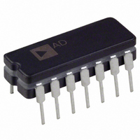
OP400FY Analog Devices Inc, OP400FY Datasheet - Page 7

OP400FY
Manufacturer Part Number
OP400FY
Description
IC OPAMP GP 500KHZ QUAD 14CDIP
Manufacturer
Analog Devices Inc
Type
General Purpose Amplifierr
Specifications of OP400FY
Slew Rate
0.15 V/µs
Rohs Status
RoHS non-compliant
Amplifier Type
General Purpose
Number Of Circuits
4
Gain Bandwidth Product
500kHz
Current - Input Bias
750pA
Voltage - Input Offset
60µV
Current - Supply
600µA
Voltage - Supply, Single/dual (±)
±3 V ~ 18 V
Operating Temperature
-25°C ~ 85°C
Mounting Type
Through Hole
Package / Case
14-CDIP (0.300", 7.62mm)
Op Amp Type
Low Power
No. Of Amplifiers
4
Bandwidth
0.5MHz
Supply Voltage Range
± 3V To ± 18V
Amplifier Case Style
DIP
No. Of Pins
14
Operating Temperature Range
-25°C To
Rail/rail I/o Type
No
Number Of Elements
4
Unity Gain Bandwidth Product
0.5MHz
Common Mode Rejection Ratio
115dB
Input Offset Voltage
230uV
Input Bias Current
6nA
Single Supply Voltage (typ)
Not RequiredV
Dual Supply Voltage (typ)
±5/±9/±12/±15/±18V
Voltage Gain In Db
136.9dB
Power Supply Rejection Ratio
140dB
Power Supply Requirement
Dual
Shut Down Feature
No
Single Supply Voltage (min)
Not RequiredV
Single Supply Voltage (max)
Not RequiredV
Dual Supply Voltage (min)
±3V
Dual Supply Voltage (max)
±20V
Technology
Bipolar
Operating Temp Range
-25C to 85C
Operating Temperature Classification
Commercial
Mounting
Through Hole
Pin Count
14
Package Type
CDIP
Output Type
-
Current - Output / Channel
-
-3db Bandwidth
-
Lead Free Status / Rohs Status
Not Compliant
Available stocks
Company
Part Number
Manufacturer
Quantity
Price
0
100
800
600
400
200
10
1k
0
1
1
Figure 10. Noise Voltage Density vs. Frequency
Figure 11. Current Noise Density vs. Frequency
2
Figure 12. 0.1 Hz to 10 Hz Noise
TIME (Seconds)
10
10
4
FREQUENCY (Hz)
FREQUENCY (Hz)
6
100
100
8
T
V
A
S
= 25°C
= ±15V
10
1k
1k
Rev. G | Page 7 of 16
140
120
100
2.5
2.4
2.3
2.2
2.1
2.5
2.4
2.3
2.2
2.1
80
60
40
20
0
–75
0.1
±2
Figure 13. Total Supply Current vs. Supply Voltage
FOUR AMPLIFIERS
T
FOUR AMPLIFIERS
V
Figure 15. Power Supply Rejection vs. Frequency
Figure 14. Total Supply Current vs. Temperature
A
S
= 25°C
= ±15V
–50
±4
1
–25
±6
POSITIVE
SUPPLY
±8
10
SUPPLY VOLTAGE (V)
0
TEMPERATURE (°C)
FREQUENCY (Hz)
±10
25
100
±12
50
±14
75
1k
±16
100
NEGATIVE
SUPPLY
10k
±18
125
OP400
100k
150
±20


