HA7-2520-2 Intersil, HA7-2520-2 Datasheet
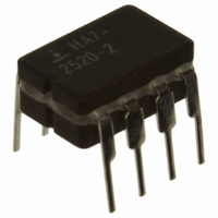
IC OPAMP 20MHZ 120V/US 8-DIP

HA7-2520-2

Manufacturer Part Number
HA7-2520-2
Description
IC OPAMP 20MHZ 120V/US 8-DIP
Manufacturer
Intersil
Datasheet

Specifications of HA7-2520-2

Amplifier Type
General Purpose
Number Of Circuits
1
Slew Rate
120 V/µs
Gain Bandwidth Product
20MHz
Current - Input Bias
100nA
Voltage - Input Offset
4000µV
Current - Supply
4mA
Current - Output / Channel
20mA
Voltage - Supply, Single/dual (±)
8 V ~ 36 V, ±4 V ~ 18 V
Operating Temperature
-55°C ~ 125°C
Mounting Type
Through Hole
Package / Case
8-CDIP (0.300", 7.62mm)
Lead Free Status / RoHS Status
Contains lead / RoHS non-compliant
Output Type
-
-3db Bandwidth
-

Available stocks

Company
Part Number
Manufacturer
Quantity
Price
Part Number:
HA7-2520-2
Manufacturer:
INTERSIL
Quantity:
3 086
Part Number:
HA7-2520-2
Manufacturer:
intel
Quantity:
780
Part Number:
HA7-2520-2
Manufacturer:
INTERS
Quantity:
596
20MHz, High Slew Rate, Uncompensated,
High Input Impedance, Operational
Amplifiers
HA-2520, HA-2522, HA-2525 comprise a series of operational
amplifiers delivering an unsurpassed combination of
specifications for slew rate, bandwidth and settling time. These
dielectrically isolated amplifiers are controlled at close loop
gains greater than 3 without external compensation. In addition,
these high performance components also provide low offset
current and high input impedance.
120V/ms slew rate and 200ns (0.2%) settling time of these
amplifiers make them ideal components for pulse amplification
and data acquisition designs. These devices are valuable
components for RF and video circuitry requiring up to 20MHz
gain bandwidth and 2MHz power bandwidth. For accurate signal
conditioning designs the HA-2520, HA-2522, HA-2525’s
superior dynamic specifications are complemented by 10nA
offset current, 100MΩ input impedance and offset trim capability.
Ordering Information
NOTES:
*Pb-Free PDIPs can be used for through hole wave solder processing only.
They are not intended for use in Reflow solder processing applications.
HA2-2520-2
HA7-2520-2
HA2-2522-2
HA2-2525-5
HA3-2525-5
HA2-2525-
5ZR5254*
(Note 2)
HA3-2525-5Z
(Note 1)
HA7-2525-5
HA9P2525-5
HA9P2525-5Z
(Note 1)
1. These Intersil Pb-free plastic packaged products employ special Pb-free
2. These Intersil Pb-free Hermetic packaged products employ 100% Au
NUMBER
material sets, molding compounds/die attach materials, and 100%
matte tin plate plus anneal (e3 termination finish, which is RoHS
compliant and compatible with both SnPb and Pb-free soldering
operations). Intersil Pb-free products are MSL classified at Pb-free peak
reflow temperatures that meet or exceed the Pb-free requirements of
IPC/JEDEC J STD-020
plate - e4 termination finish, which is RoHS compliant and compatible
with both SnPb and Pb-free soldering operations.
PART
HA2- 2520-2
HA7-2520-2
HA2- 2522-2
HA2- 2525-5
HA3- 2525-5
HA2-252-5ZR5254
HA3- 2525-5Z
HA7- 2525-5
2525 5
2525 -5Z
MARKING
PART
®
1
-55 to +125 8 Ld Metal Can T8.C
-55 to +125 8 Ld CerDIP
-55 to +125 8 Ld Metal Can T8.C
0 to +75
0 to +75
0 to +75
0 to +75
0 to +75
0 to +75
RANGE
0 to +75
TEMP.
Data Sheet
(°C)
8 Ld Metal Can T8.C
8 Ld PDIP
8 Ld Metal Can T8.C
8 Ld PDIP*
(Pb-Free)
8 Ld CerDIP
8 Ld SOIC
8 Ld SOIC
(Pb-Free)
PACKAGE
1-888-INTERSIL or 1-888-468-3774
CAUTION: These devices are sensitive to electrostatic discharge; follow proper IC Handling Procedures.
F8.3A
E8.3
E8.3
F8.3A
M8.15
M8.15
DWG.
PKG.
NO.
Features
• High Slew Rate . . . . . . . . . . . . . . . . . . . . . . . . . . 120V/µs
• Fast Settling . . . . . . . . . . . . . . . . . . . . . . . . . . . . . . . 200ns
• Full Power Bandwidth . . . . . . . . . . . . . . . . . . . . . . . 2MHz
• Gain Bandwidth (A
• High Input Impedance . . . . . . . . . . . . . . . . . . . . . . 100MΩ
• Low Offset Current . . . . . . . . . . . . . . . . . . . . . . . . . . .10nA
• Compensation Pin for Unity Gain Capability
• Pb-Free Available (RoHS Compliant)
Applications
• Data Acquisition Systems
• RF Amplifiers
• Video Amplifiers
• Signal Generators
Pinouts
Copyright Intersil Americas Inc. 1999, 2004, 2005, 2006, 2009. All Rights Reserved
February 16, 2009
HA-2520, HA-2522, HA-2525
All other trademarks mentioned are the property of their respective owners.
|
Intersil (and design) is a registered trademark of Intersil Americas Inc.
(8 LD CERDIP, 8 LD PDIP, 8 LD SOIC)
BAL
IN-
+IN
-IN
BAL
HA-2520, HA-2522, HA-2525
V-
IN+
2
V
1
2
3
4
(8 LD METAL CAN)
HA-2520, HA-2525
1
3
≥ 3) . . . . . . . . . . . . . . . . . . . . 20MHz
TOP VIEW
TOP VIEW
COMP
+
-
-
+
8
4
V-
5
7
8
7
6
5
6
V+
BAL
COMP
V+
OUT
BAL
OUT
FN2894.9

Related parts for HA7-2520-2

HA7-2520-2 Summary of contents

Page 1

... Ordering Information TEMP. PART PART RANGE NUMBER MARKING (°C) HA2-2520-2 HA2- 2520-2 -55 to +125 8 Ld Metal Can T8.C HA7-2520-2 HA7-2520-2 -55 to +125 8 Ld CerDIP HA2-2522-2 HA2- 2522-2 -55 to +125 8 Ld Metal Can T8.C HA2-2525-5 HA2- 2525 +75 HA3-2525-5 HA3- 2525 +75 HA2-2525- HA2-252-5ZR5254 ...

Page 2

... Maximum Junction Temperature (Plastic Package +150°C Maximum Storage Temperature Range . . . . . . . . . -65°C to +150°C Pb-Free Reflow Profile .see link below http://www.intersil.com/pbfree/Pb-FreeReflow.asp *Pb-free PDIPs can be used for through hole wave solder processing only. They are not intended for use in Reflow solder processing applications. = ± ...

Page 3

Electrical Specifications V SUPPLY TEMP PARAMETER (°C) Slew Rate (Notes 6, 10, 13, 15) Settling Time (Notes 6, 10, 13, 15) POWER SUPPLY CHARACTERISTICS Supply Current Power Supply Rejection Ratio (Note 11) Full NOTES: 5. This parameter value is based ...

Page 4

Test Circuits and Waveforms +1.67V INPUT -1.67V +5V 75% ΔV OUTPUT 25% -5V SLEW Δt RATE = ΔV/Δt SETTLING TIME FIGURE 1. SLEW RATE AND SETTLING TIME + IN - 5pF 1333Ω 667Ω FIGURE 3. SLEW RATE AND TRANSIENT RESPONSE ...

Page 5

Schematic Diagram OFFSET PIN +INPUT Typical ...

Page 6

Typical Performance Curves -60 -40 - TEMPERATURE (°C) FIGURE 8. OFFSET VOLTAGE vs TEMPERATURE (6 TYPICAL UNITS FROM 3 LOTS -10 -20 ...

Page 7

Typical Performance Curves 5.4 5.2 5.0 4.8 4.6 4.4 4.2 4.0 3.8 3.6 3.4 3.2 3.0 2.8 2.6 2 SUPPLY VOLTAGE (±V) FIGURE 14. SUPPLY CURRENT vs SUPPLY VOLTAGE 100 100pF 300pF ...

Page 8

Die Characteristics SUBSTRATE POTENTIAL: Unbiased Metallization Mask Layout COMP BAL 8 HA-2520, HA-2522, HA-2525 TRANSISTOR COUNT: 40 PROCESS: Bipolar Dielectric Isolation HA-2520, HA-2522, HA-2525 V+ OUT -IN +IN BAL V- FN2894.9 February 16, 2009 ...

Page 9

Metal Can Packages (Can) REFERENCE PLANE Ø ØD ØD1 Øb1 Øb F BASE AND Q SEATING PLANE BASE METAL LEAD FINISH Øb1 Øb2 SECTION A-A NOTES: 1. (All leads) Øb applies between L1 ...

Page 10

Ceramic Dual-In-Line Frit Seal Packages (CERDIP) -D- -A- E -B- bbb BASE Q PLANE -C- SEATING PLANE aaa ccc ...

Page 11

Dual-In-Line Plastic Packages (PDIP INDEX N/2 AREA -B- -A- D BASE PLANE -C- SEATING PLANE 0.010 (0.25 NOTES: 1. Controlling Dimensions: INCH. In case of conflict between ...

Page 12

... Accordingly, the reader is cautioned to verify that data sheets are current before placing orders. Information furnished by Intersil is believed to be accurate and reliable. However, no responsibility is assumed by Intersil or its subsidiaries for its use; nor for any infringements of patents or other rights of third parties which may result from its use ...

Related keywords