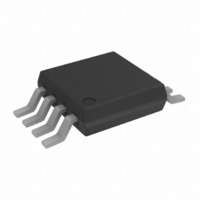
AD822ARM-R2 Analog Devices Inc, AD822ARM-R2 Datasheet - Page 11

AD822ARM-R2
Manufacturer Part Number
AD822ARM-R2
Description
IC OPAMP GP R-R 1.9MHZ LP 8MSOP
Manufacturer
Analog Devices Inc
Datasheet
1.AD822ARMZ-REEL.pdf
(24 pages)
Specifications of AD822ARM-R2
Rohs Status
RoHS non-compliant
Design Resources
16-Bit Fully Isolated 4 mA to 20 mA Output Module Using AD5662, ADuM1401, and External Amplifiers (CN0064)
Amplifier Type
General Purpose
Number Of Circuits
2
Output Type
Rail-to-Rail
Slew Rate
3 V/µs
Gain Bandwidth Product
1.9MHz
-3db Bandwidth
1.9MHz
Current - Input Bias
2pA
Voltage - Input Offset
400µV
Current - Supply
1.4mA
Current - Output / Channel
20mA
Voltage - Supply, Single/dual (±)
3 V ~ 36 V, ±1.5 V ~ 18 V
Operating Temperature
-40°C ~ 85°C
Mounting Type
Surface Mount
Package / Case
8-MSOP, Micro8™, 8-uMAX, 8-uSOP,
TYPICAL PERFORMANCE CHARACTERISTICS
Figure 5. Typical Distribution of Offset Voltage Drift (100 Units)
50
45
40
35
30
25
20
15
10
Figure 6. Typical Distribution of Input Bias Current (213 Units)
70
60
50
40
30
20
10
16
14
12
10
–0.5
8
6
4
2
0
5
0
0
–12
Figure 4. Typical Distribution of Offset Voltage (390 Units)
0
–0.4
–10
1
–0.3
–8
2
–6
–0.2
OFFSET VOLTAGE DRIFT (µV/°C)
INPUT BIAS CURRENT (pA)
3
OFFSET VOLTAGE (mV)
–4
–0.1
4
–2
0
5
0
0.1
6
2
0.2
7
4
V
V
V
0.3
S
S
S
8
= ±5V
= ±15V
= 0V, 5V
6
0.4
9
8
0.5
10
10
Rev. I | Page 11 of 24
Figure 7. Input Bias Current vs. Common-Mode Voltage; V
Figure 8. Input Bias Current vs. Common-Mode Voltage; V
100k
10k
100
Figure 9. Input Bias Current vs. Temperature; V
100
0.1
0.1
–5
1k
10
1k
10
5
0
1
1
–5
–16
20
V
–4
–12
S
= ±5V
40
–3
–8
COMMON-MODE VOLTAGE (V)
COMMON-MODE VOLTAGE (V)
–2
V
S
60
= 0V, +5V AND ±5V
TEMPERATURE (°C)
–4
–1
V
S
= ±5 V
80
0
0
1
4
100
2
8
S
= 5 V, V
3
120
S
12
= 5 V, 0 V, and
4
CM
S
= ±15 V
AD822
= 0 V
140
16
5


