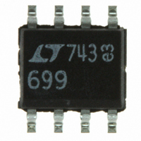
LTC699CS8#PBF Linear Technology, LTC699CS8#PBF Datasheet - Page 4

LTC699CS8#PBF
Manufacturer Part Number
LTC699CS8#PBF
Description
IC MPU SUPERVISORY CIRCUIT 8SOIC
Manufacturer
Linear Technology
Type
Simple Reset/Power-On Resetr
Datasheet
1.LTC699CN8PBF.pdf
(4 pages)
Specifications of LTC699CS8#PBF
Number Of Voltages Monitored
1
Output
Open Drain or Open Collector
Reset
Active Low
Reset Timeout
140 ms Minimum
Voltage - Threshold
4.65V
Operating Temperature
0°C ~ 70°C
Mounting Type
Surface Mount
Package / Case
8-SOIC (3.9mm Width)
Lead Free Status / RoHS Status
Lead free / RoHS Compliant
Available stocks
Company
Part Number
Manufacturer
Quantity
Price
PACKAGE DESCRIPTIO
LTC699
A
4
Watchdog Timer
The LTC699 provides a watchdog timer function to moni-
tor the activity of the microprocessor. If the microproces-
sor does not toggle the Watchdog Input (WDI) within the
time-out period, RESET is forced to active low for a
minimum of 140ms. The watchdog time-out period is
fixed at a 1.0 second minimum on the LTC699, which is
adequate time for most systems to service the watchdog
timer immediately after a reset. Figure 2 shows the timing
diagram of watchdog time-out period and reset active
time. The watchdog time-out period is restarted as soon
PPLICATI
SYMBOL
A
A
B
B
C
D
E
1
1
e
E
A
INCHES
0.130 ± 0.006
0.020 MIN
0.018 ± 0.003
0.045 – 0.065
0.009 – 0.015
0.400 MAX
0.300 – 0.320
C
Linear Technology Corporation
1630 McCarthy Blvd., Milpitas, CA 95035-7487
(408) 432-1900
MILLIMETERS
3.302 ± 0.127
0.508 MIN
0.457 ± 0.076
1.143 – 1.651
0.229 – 0.381
10.160 MAX
7.620 – 8.128
S
Q
8-Lead Plastic DIP
1
O
WDI
RESET
RESET
V
CC
B
N8 Package
1
V
U
FAX
= 5V
CC
: (408) 434-0507
S
SYMBOL
E
e
e
L
Q
S
1
A
1
1
e
1
I FOR ATIO
U
INCHES
0.250 ± 0.010
0.325 + 0.025
0.100 ± 0.010
0.125 MIN
0.065 TYP
0.045 ± 0.015
V2
–0.015
Figure 2. Watchdog Time-Out Period and Reset Active Time
L
t1
A
B
TELEX
t1
MILLIMETERS
6.350 ± 0.254
8.255 + 0.635
2.540 ± 0.254
3.175 MIN
1.651 TYP
1.143 ± 0.381
A
1
W
–0.381
: 499-3977
U
8
1
Dimensions in inches (millimeters) unless otherwise noted.
7
2
110 C
T
JMAX
D
Figure 1. Reset Active Time
t2
6
3
U
130 C/W
t1 = RESET ACTIVE TIME
t2 = WATCHDOG TIME-OUT PERIOD
5
4
JA
V1
N8 1191
E
1
t1
SYMBOL
A
A
B
C
D
E
V2
1
as RESET is inactive. When either a high-to-low or low-to-
high transition occurs at the WDI pin prior to time-out, the
watchdog time is reset and begins to time out again. To
ensure the watchdog time does not time out, either a high-
to-low or low-to-high transition on the WDI pin must
occur at or less than the minimum time-out period. If the
input to the WDI pin remains either high or low, reset
pulses will be issued every 1.6 seconds typically. The
watchdog time can be deactivated by floating the WDI pin.
The timer is also disabled when V
voltage threshold.
T
110 C
JMAX
INCHES
0.053 – 0.069
0.004 – 0.010
0.014 – 0.019
0.008 – 0.010
0.189 – 0.197
0.150 – 0.157
V1 = RESET VOLTAGE THRESHOLD
V2 = RESET VOLTAGE THRESHOLD +
RESET THRESHOLD HYSTERESIS
t1 = RESET ACTIVE TIME
180 C/W
t2
h
t1
45
JA
MILLIMETERS
1.346 – 1.753
0.102 – 0.254
0.356 – 0.483
0.203 – 0.254
4.801 – 5.004
3.810 – 3.988
L
CONDITIONS: PCB MOUNT ON FR4 MATERIAL,
STILL AIR AT 25 C, COPPER TRACE
C
8-Lead Plastic SOIC
t1
SYMBOL
e
H
h
L
A
S8 Package
INCHES
0.050 TYP
0.228 – 0.244
0.010 – 0.020
0.016 – 0.050
B
0° – 8° TYP
LTC699 F02
LINEAR TECHNOLOGY CORPORATION 1992
MILLIMETERS
1.270 TYP
5.791 – 6.198
0.254 – 0.508
0.406 – 1.270
e
1
V1
CC
A
LTC699 F01
1
falls below the reset
H
LT/GP 0192 10K REV 0
8
1
7
2
D
6
3
5
4
S8 1191
E


