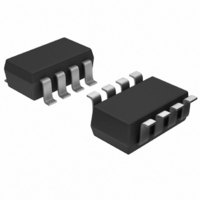
MAX6752KA29+T Maxim Integrated Products, MAX6752KA29+T Datasheet - Page 6

MAX6752KA29+T
Manufacturer Part Number
MAX6752KA29+T
Description
IC RESET MPU W/ADJ RESET SOT23-8
Manufacturer
Maxim Integrated Products
Type
Simple Reset/Power-On Resetr
Datasheet
1.MAX6749KAT.pdf
(14 pages)
Specifications of MAX6752KA29+T
Number Of Voltages Monitored
1
Output
Push-Pull, Totem Pole
Reset
Active Low
Reset Timeout
Adjustable/Selectable
Voltage - Threshold
2.925V
Operating Temperature
-40°C ~ 125°C
Mounting Type
Surface Mount
Package / Case
SOT-23-8
Monitored Voltage
1.575 V to 5 V
Output Type
Active Low, Push-Pull
Manual Reset
Not Resettable
Watchdog
Watchdog
Battery Backup Switching
No Backup
Supply Voltage (max)
5.5 V
Supply Voltage (min)
1 V
Supply Current (typ)
5 uA
Maximum Power Dissipation
714 mW
Maximum Operating Temperature
+ 125 C
Mounting Style
SMD/SMT
Minimum Operating Temperature
- 40 C
Power Fail Detection
No
Undervoltage Threshold
2.867 V
Overvoltage Threshold
2.984 V
Power-up Reset Delay (typ)
9.487 ms
Lead Free Status / RoHS Status
Lead free / RoHS Compliant
Other names
MAX6752KA29+T
MAX6752KA29+TTR
MAX6752KA29+TTR
µP Reset Circuits with Capacitor-Adjustable
Reset/Watchdog Timeout Delay
6
MAX6746
MAX6747
_______________________________________________________________________________________
—
5
6
7
8
MAX6748–
MAX6751
PIN
—
5
6
7
8
MAX6752
MAX6753
—
5
6
7
8
RESET
NAME
SET1
WDS
WDI
V
CC
Watchdog Select Input. WDS selects the watchdog mode. Connect
WDS to ground to select normal mode and the watchdog timeout
period. Connect WDS to V
basic timeout period by a factor of 128. A change in the state of WDS
clears the watchdog timer.
Logic Input. SET1 selects the watchdog window ratio or disables the
watchdog timer. See Table 1.
Watchdog Input.
MAX6746–MAX6751: A falling transition must occur on WDI within the
selected watchdog timeout period or a reset pulse occurs. The
watchdog timer clears when a transition occurs on WDI or whenever
RESET is asserted. Connect SWT to ground to disable the watchdog
timer function.
MAX6752/MAX6753: WDI falling transitions within periods shorter than
t
period. The watchdog timer begins to count after RESET is deasserted.
The watchdog timer clears when a valid transition occurs on WDI or
whenever RESET is asserted. Connect SET0 high and SET1 low to
disable the watchdog timer function. See the Watchdog Timer section.
Push/Pull or Open-Drain Reset Output. RESET asserts whenever V
RESET IN drops below the selected reset threshold voltage (V
V
low for the reset timeout period after all reset conditions are deasserted,
and then goes high. The watchdog timer triggers a reset pulse (t
whenever a watchdog fault occurs.
Supply Voltage. V
threshold V
WD1
RESET IN
or longer than t
, respectively) or manual reset is pulled low. RESET remains
CC
monitor.
CC
WD2
is the power-supply input and the input for fixed
Pin Description (continued)
force RESET to assert low for the reset timeout
CC
to select extended mode, multiplying the
FUNCTION
TH
RP
or
CC
)
or


