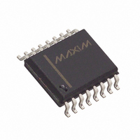
MAX696EWE+ Maxim Integrated Products, MAX696EWE+ Datasheet - Page 6

MAX696EWE+
Manufacturer Part Number
MAX696EWE+
Description
IC SUPERVISOR MPU 16-SOIC
Manufacturer
Maxim Integrated Products
Type
Battery Backup Circuitr
Datasheet
1.MAX696EWE.pdf
(15 pages)
Specifications of MAX696EWE+
Number Of Voltages Monitored
2
Output
Push-Pull, Push-Pull
Reset
Active High/Active Low
Reset Timeout
35 ms Minimum
Voltage - Threshold
Adjustable/Selectable
Operating Temperature
-40°C ~ 85°C
Mounting Type
Surface Mount
Package / Case
16-SOIC (0.300", 7.5mm Width)
Monitored Voltage
3 V to 5.5 V
Undervoltage Threshold
Adj V
Overvoltage Threshold
Adj V
Manual Reset
No
Watchdog
Yes
Battery Backup Switching
Yes
Power-up Reset Delay (typ)
70 ms
Supply Voltage (max)
5.5 V
Supply Voltage (min)
3 V
Supply Current (typ)
300 uA
Maximum Power Dissipation
600 mW
Mounting Style
SMD/SMT
Maximum Operating Temperature
+ 85 C
Chip Enable Signals
No
Minimum Operating Temperature
- 40 C
Output Type
Active High or Active Low or Push-Pull
Power Fail Detection
Yes
Lead Free Status / RoHS Status
Lead free / RoHS Compliant
A typical connection for the MAX696 is shown in Figure
1. CMOS RAM is powered from V
connected to V
when V
ply 50mA from V
external pnp transistor can be added. When V
er than V
Microprocessor Supervisory Circuits
Figure 1. MAX696 Typical Application
6
MAX696
_______________________________________________________________________________________
—
—
—
CC
BATT
is less than the battery voltage. V
PIN
INPUT
+5V
V
, the BATT ON output goes low, providing
CC
CC
MAX697
CC
0.1µF
12
13
1
when power is present, or to V
, but if more current is required, an
BATTERY
RESET
3V
Typical Applications
NO CONNECTION
CE OUT
NAME
CE IN
TEST
OUT
13
. V
1
9
4
7
8
V
GND
PFI
OSC IN
OSC SEL
LL
OUT
BATT
IN
Used During Maxim Manufacture Only. Always ground this pin.
CE OUT goes low only when CE IN is low and LL
The Input to the CE Gating Circuit. Connect to GND or V
LOW LINE
OUT
SYSTEM STATUS INDICATORS
V
is internally
CC
MAX696
CC
6
3
can sup-
is high-
BATT
MAX696
BATT ON
WDO
5
14
7mA of base drive for the external transistor. When V
is lower than V
the backup battery to V
battery-backup mode is 1µA maximum when V
between 0V and (V
A voltage detector monitors V
output to hold the microprocessor’s RESET line low when
LL
IN
is below 1.3V. An internal monostable holds RESET
AUDIBLE
ALARM
RESET
RESET
V
PFO
WDI
OUT
Pin Description (continued)
FUNCTION
11
10
15
18
BATT
2
BATT
, an internal 200Ω MOSFET connects
0.1µF
OUT
IN
- 700mV).
OTHER SYSTEM RESET SOURCES
is above 1.3V. See Figure 5.
. The quiescent current in the
CC
OUT
and generates a RESET
I/O
if not used.
NMI
RESET
CMOS
RAM
MICROPROCESSOR
Reset Output
A0–A15
CC
CC
is


