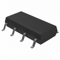
MB3793-42PNF-G-JN-6E1 Fujitsu Semiconductor America Inc, MB3793-42PNF-G-JN-6E1 Datasheet - Page 4

MB3793-42PNF-G-JN-6E1
Manufacturer Part Number
MB3793-42PNF-G-JN-6E1
Description
IC PWR SUPP MON DUAL WD 8SOP
Manufacturer
Fujitsu Semiconductor America Inc
Type
Simple Reset/Power-On Resetr
Datasheet
1.MB3793-42PNF-ER-6E1.pdf
(23 pages)
Specifications of MB3793-42PNF-G-JN-6E1
Number Of Voltages Monitored
1
Output
CMOS Inverted
Reset
Active Low
Reset Timeout
80 ms Minimum
Voltage - Threshold
4.2V
Operating Temperature
-40°C ~ 85°C
Mounting Type
Surface Mount
Package / Case
8-SOP
Lead Free Status / RoHS Status
Lead free / RoHS Compliant
Other names
865-1028-2
4
MB3793-42
1. Comp. S
2. Comp. O
3. Reset output buffer
4. Pulse generator
5. Watchdog timer
6. Inhibition terminal
7. Flip-flop circuit
BLOCK FUNCTIONS
Comp. S is a comparator with hysteresis to compare the reference voltage with a voltage (V
of dividing the power voltage (V
This function enables the MB3793 to detect an abnormality within 1 s when the power is cut or falls abruptly.
Comp. O is a comparator to control the reset signal (RESET) output and compares the threshold voltage with
the voltage at the CTP terminal for setting the power-on reset hold time. When the voltage at the CTP terminal
exceeds the threshold voltage, resetting is canceled.
Since the reset (RESET) output buffer has CMOS organization, no pull-up resistor is needed.
The pulse generator generates pulses when the voltage at the CK1 and CK2 clock terminals changes to High
from Low level (positive-edge trigger) and exceeds the threshold voltage; it sends the clock signal to the watchdog
timer.
The watchdog timer can monitor two clock pulses. Short-circuit the CK1 and CK2 clock terminals to monitor a
single clock pulse.
The inhibition (INH) terminal forces the watchdog timer on/off. When this terminal is High level, the watchdog
timer is stopped.
The flip-flop circuit RSFF1 controls charging and discharging of the power-on reset hold time setting capacity
(C
circuit only functions during resetting and does not function at power-on reset.
TP
). The flip-flop circuit RSFF2 switches the charging accelerator for charging C
CC
) by resistors R
1
and R
2
. When V
S
falls below 1.24 V, a reset signal is output.
TP
during resetting on/off. This
S
) that is the result


