T83-A350X EPCOS Inc, T83-A350X Datasheet - Page 13
T83-A350X
Manufacturer Part Number
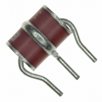
T83-A350X
Description
SURGE ARRESTER 350V GASTUBE 3PIN
Manufacturer
EPCOS Inc
Datasheet
1.T83-A350X.pdf
(71 pages)
Specifications of T83-A350X
Spark Over Voltage
350V
Tolerance
±20%
Impulse Discharge Current
10kA 8x20µs
Package / Case
Radial - 3 Lead
Mounting Type
Through Hole
Lead Free Status / RoHS Status
Lead free / RoHS Compliant
Other names
495-2635
B88069X8690B502
B88069X8690B502
Available stocks
Company
Part Number
Manufacturer
Quantity
Price
Company:

Part Number:
T83-A350XF4
Manufacturer:
Raychem
Quantity:
8 081


Applications
Anwendungen
Protective circuits
The following basic circuits illustrate standard configura-
tions for surge arresters used in protection circuits for the
telecommunications sector. 3-point protection solutions
contain only an arrester whereas 5-point protection solu-
tions make additional use of current-limiting components
such as PTC thermistors.
3-point protection
3-point protection circuits are connected between the a/b
wires and ground and operate by conducting the voltage
surge to ground. Both 2-electrode
trode arresters
mechanism
For further information about this variant see page 22.
5-point protection
A 5-point protection circuit contains a current-limiting
component, usually a PTC thermistor, in addition to the
arrester. The thermistor blocks further current flow
through it by assuming a very high resistance in the event
of an overcurrent.
Figs. 7
arresters, while
safe mechanism (for details refer to page 22). However, it
may not always be possible to reset an activated ther-
mistor in systems with constant current feed.
© EPCOS AG 2008
Basic circuit configurations
Grundschaltungen
a
b
a
b
and
(Figs. 5
8
(Fig.
Figs. 9
show circuits with 2 and 3-electrode
Fig. / Bild 3
Fig. / Bild 7
and 6) represent another alternative.
4) are used. Arresters with a failsafe
RAB0205-Y
RAB0209-E
Ground
Erde
Ground
Erde
and
a’
b’
a’
b’
Please read Important notes on page 4 and Cautions and warnings on page 69.
10
show variants with a fail-
a
b
a
b
(Fig.
3) and 3-elec-
Fig. / Bild 4
Fig. / Bild 8
Bitte beachten Sie die Seite 4 Wichtige Hinweise sowie die
RAB0210-R
RAB0206-G
Ground
Erde
Ground
Erde
a’
b’
a’
b’
Warn- und Sicherheitshinweise auf Seite 69.
a
b
a
b
Schutzschaltungen
Die folgenden Grundschaltungen beschreiben die übli-
chen Anordnungen für Ableiter in Schutzschaltungen im
Telekombereich. Bei alleiniger Verwendung eines Ablei-
ters spricht man in der Praxis vom 3-Punkt-Schutz. Wer-
den zusätzlich strombegrenzende Bauteile eingesetzt, so
spricht man von einer 5-Punkt-Schutzlösung.
3-Punkt-Schutz
Der 3-Punkt-Schutz wirkt zwischen a-Ader/b-Ader und
Erde. Die Überspannung wird dabei gegen Erde abgelei-
tet. Es kommen sowohl 2-Elektroden-
3-Elektroden-Ableiter
Kurzschlussmechanismus
tere Option. Näheres hierzu siehe Seite 22.
5-Punkt-Schutz
Beim 5-Punkt-Schutz wird zusätzlich zum Überspan-
nungsableiter ein strombegrenzendes Bauteil – heute in
der Regel ein Kaltleiter – in den Stromkreis eingefügt. Der
Kaltleiter riegelt im Beeinflussungsfall den weiteren
Stromfluss in die Schaltung ab, indem er einen sehr
hohen Widerstandswert annimmt.
Bild 7
den-Ableitern,
schlussmechanismus (siehe hierzu auch Seite 22). Bei
Systemen mit Konstantstrom-Einspeisung kann sich
jedoch ein aktivierter Kaltleiter u. U. nicht zurücksetzen.
und
Fig. / Bild 5
Fig. / Bild 9
8
zeigen den Aufbau mit 2- bzw. 3-Elektro-
RAB0207-O
RAB0211-Z
Bild 9
Ground
Erde
Ground
Erde
a’
b’
a’
b’
(Bild
und
a
b
a
b
(Bild 5
4) zum Einsatz. Ableiter mit
10
die Variante mit Kurz-
und 6) bieten eine wei-
Fig. / Bild 10
Fig. / Bild 6
(Bild
13
RAB0208-W
RAB0212-H
Ground
Erde
Ground
Erde
b’
a’
3) als auch
a’
b’
Related parts for T83-A350X
Image
Part Number
Description
Manufacturer
Datasheet
Request
R

Part Number:
Description:
SURGE ARRESTER 90V GASTUBE 3PIN
Manufacturer:
EPCOS Inc
Datasheet:

Part Number:
Description:
SURGE ARRESTER 230V GASTUBE 3PIN
Manufacturer:
EPCOS Inc
Datasheet:


Part Number:
Description:
CAP .15UF 63V METAL POLY
Manufacturer:
EPCOS Inc
Datasheet:


Part Number:
Description:
CAP .01UF 400V METAL POLY
Manufacturer:
EPCOS Inc
Datasheet: