DS1819AR-10/T&R Maxim Integrated Products, DS1819AR-10/T&R Datasheet
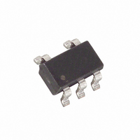
IC MICROMON 3V W/PBRST SOT-23-5

DS1819AR-10/T&R

Manufacturer Part Number
DS1819AR-10/T&R
Description
IC MICROMON 3V W/PBRST SOT-23-5
Manufacturer
Maxim Integrated Products
Series
MicroMonitor™r
Type
Simple Reset/Power-On Resetr
Datasheet

Specifications of DS1819AR-10/T&R

Number Of Voltages Monitored
1
Output
Push-Pull, Totem Pole
Reset
Active Low
Reset Timeout
140 ms Minimum
Voltage - Threshold
2.925V
Operating Temperature
-40°C ~ 85°C
Mounting Type
Surface Mount
Package / Case
SOT-23-5, SC-74A, SOT-25
Lead Free Status / RoHS Status
Contains lead / RoHS non-compliant

Available stocks

Company
Part Number
Manufacturer
Quantity
Price
Part Number:
DS1819AR-10/T&R
Manufacturer:
ITT
Quantity:
3 170
FEATURES
§ Halts and restarts an out-of-control
§ Holds microprocessor in check during power
§ Automatically restarts microprocessor after
§ Monitors pushbutton for external override
§ Accurate 5%, 10%, or 20% (3V only)
§ Eliminates the need for discrete components
§ 20% tolerance for use with 3.0V systems
§ Pin- and function-compatible with the
§ Low cost SOT-23-5 package
§ Industrial temperature range: -40°C to +85°C
x = "DS1814" for 5V devices
x = "DS1819" for 3V devices
DESCRIPTION
The DS1814 5-Volt MicroMonitor and the DS1819 3.3V MicroMonitor monitor three vital conditions for
a microprocessor: power supply, software execution, and external override. First, a precision temperature-
compensated reference and comparator circuit monitor the status of V
condition occurs, an internal power-fail signal is generated which forces the reset(s) to an active state.
When V
140ms to allow the power supply and processor to stabilize.
www.maxim-ic.com
DEVICE
DS181xA
DS181xB
DS181xC
microprocessor
transients
power failure
microprocessor power monitoring
MAX823/24/25 products
CC
returns to an in-tolerance condition, the reset signal is kept in the active state for a minimum of
RST
X
X
X
RST
X
X
PBRST
X
X
WD
X
X
1 of 8
PIN ASSIGNMENT
PIN DESCRIPTION
DS181xA
1
2
3
4
5
DS181xB
1
2
3
4
5
DS181xC
1
2
3
4
5
5V and 3.3V MicroMonitor
GND
VCC
GND
RST
VCC
GND
RST
VCC
ST
ST
RST
PBRST
RST
RST
PBRST
SOT-23-5 PACKAGE
See Mech. Drawing
3
4
Active Low Reset Output
Ground
Pushbutton Reset Input
Strobe Input
Power Supply
Active Low Reset Output
Ground
Active High Reset Output
Strobe Input
Power Supply
Active Low Reset Output
Ground
Active High Reset Output
Pushbutton Reset Input
Power Supply
CC
2
. When an out-of-tolerance
DS1814/DS1819
1
5
122001

Related parts for DS1819AR-10/T&R

DS1819AR-10/T&R Summary of contents

Page 1

FEATURES § Halts and restarts an out-of-control microprocessor § Holds microprocessor in check during power transients § Automatically restarts microprocessor after power failure § Monitors pushbutton for external override § Accurate 5%, 10%, or 20% (3V only) microprocessor power ...

Page 2

The DS1814/DS1819 ‘A’ and ‘C’ perform pushbutton reset control. They debounce the pushbutton input and generate an active reset pulse width of 140ms minimum. The DS1814/9 ‘A’ and ‘B’ versions perform a watchdog function. The watchdog is an internal timer ...

Page 3

DS1814/DS1819 BLOCK DIAGRAM Figure 1 *Notes: available on'A' and 'B' versions ST available on 'A' and 'C' versions PBRST RST available on 'B' and 'C' versions PUSHBUTTON RESET Figure 2 TIMING DIAGRAM: PUSHBUTTON RESET Figure DS1814/DS1819 ...

Page 4

WATCHDOG TIMER Figure 4 TIMING DIAGRAM: STROBE INPUT Figure 5 WATCHDOG DISABLE CIRCUIT Figure 6 TIMING DIAGRAM: POWER-DOWN Figure DS1814/DS1819 ...

Page 5

TIMING DIAGRAM: POWER-UP Figure 8 VALID TO 0 VOLTS V RST OUTPUT VALID CONDITIONS The output uses a push-pull output which can maintain a valid output down to 1.0V V RST current below 1.0V a resistor can be connected form ...

Page 6

ABSOLUTE MAXIMUM RATINGS* Voltage on V Pin Relative to Ground CC Voltage on I/O Relative to Ground Operating Temperature Range Storage Temperature Range Soldering Temperature * This is a stress rating only and functional operation of the device at these ...

Page 7

AC ELECTRICAL CHARACTERISTICS PARAMETER = V PBRST IL Reset Active Time Pulse Width ST Watchdog Time-out V Detect to RST and RST CC V Slew Rate (rising edge Detect to RST and RST CC Stable Low to RST ...

Page 8

PART MARKING CODES ‘A’, ‘B’ and ‘C’ represents the Device Type. 14A - DS1814A 14B - DS1814B 14C - DS1814C 19A - DS1819A 19B - DS1819B 19C - DS1819C SOT-23-5 PACKAGE ‘D’ represents the Device Tolerance ...

Related keywords