CL-210 GE Sensing, CL-210 Datasheet - Page 4
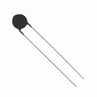
CL-210
Manufacturer Part Number
CL-210
Description
CURRENT LIMITER INRUSH
Manufacturer
GE Sensing
Series
CLr
Type
NTCr
Datasheet
1.CL-90A.pdf
(4 pages)
Specifications of CL-210
R @ 25°c
30 Ohm
R @ Current
0.60 Ohm
Current - Steady State Max
1.5A
Tolerance
±25%
Diameter
0.4" (10.2mm)
Lead Spacing
0.250" (6.35mm)
Thermistor Type
NTC
Resistance
30ohm
Thermistor Tolerance
± 25%
Operating Temperature Range
-50°C To +175°C
Thermistor Case Style
Disc
No. Of Pins
2
Steady State Current Max
1.5A
Mounting Type
Through Hole
Termination Style
Radial
Current Rating
1.5 Amps
Dimensions
10.16 mm Dia. x 5.08 mm W
Lead Free Status / RoHS Status
Lead free / RoHS Compliant
Lead Free Status / RoHS Status
Lead free / RoHS Compliant, Lead free / RoHS Compliant
Other names
235-1235
235-1235
KC021L
235-1235
KC021L


GE
Sensing
Power Thermistor
Specification
For the Reduction of Inrush Current
A power thermistor is a type of NTC thermistor used for
the reduction of large inrush currents. These large inrush
currents are typically caused by charging of filter
capacitors in switching power supplies.
g
Lead Wire Style
Y-Form
Units:
in (mm)
Power thermistor standard dimensions
D
T
©2006 GE. All rights reserved.
920-325A
All specifications are subject to change for product improvement without notice.
GE
names mentioned in this document may be trademarks or registered trademarks
of their respective companies, which are not affiliated with GE.
®
Resin coated
is a registered trademark of General Electric Co. Other company or product
H1
W1
Pb/Sn-plated
copper wire
Inside Kink: E
Outside Kink: F
Straight: D
L
Yes: J
No: M
d
F
Parts
7
9
11
13
15
18
Parts Type
Diam
(mm)
7Φ
9Φ
11Φ
13Φ
15Φ
18Φ
* The resistance tolerance is ± 10% for standard devices.
* The b constant is determined by the equation : β = 1779.7 ln (R25/R85) ...R25 and R85 represent
* For non-standard devices consult Thermometrics global business.
Code Designation
T P
1
1
2
3
4/5
6
7
8
9
10
11
the thermistor resistance at 77°F and 185°F (25ºC and 85ºC) respectively.
~
5W
TP7D7
TP8D7
TP10D7
TP16D7
TP22D7
TP5D9
TP8D9
TP10D9
TP16D9
TP4R7D11 4.7
TP5D11
TP8D11
TP10D11
TP4R7D13 4.7
TP5D13
TP8D13
TP10D13
TP3D15
TP5D15
TP8D15
TP10D15
TP4D18
TP5D18
TP8D18
TP10D18
8
2
Shape: Power thermistor
Resistance at 77°F (25°C): 8 = 8 S, 4R7 = 4.7 S
Diameter size: D7, D9, ...D18
Resistance and B constant tolerance: K: ±10%, L: ±15%
Lead wire center-to-center: (F): A: 0.19 in (5 mm), B: 0.29 in (7.5 mm),
C: 0.39 in (10 mm)
Lead wire style: D: Straight, E: Inside kink, F: Outside kink
Lead wire length: G: 0.19 in (5 mm), H: 0.27 in (7 mm), I: 0.35 in (9 mm),
...S: Other dimensions
Y-Form: J: Yes, M: No
MK part number marking: N: No, O: Yes
Packing form: Taping P: 15 pitch, Q: 30 pitch, Others: R: Bulk, S: Paper pad,
T: Element
D
7.0±1.5
9.0±1.5
11.0±1.5
13.5±1.5
15.0±1.5
18.0±1.5
D 13 L
3
Normal
no load
resistance (K)
(Ω Ω )
7
8
10
16
22
5
8
10
16
5
8
10
5
8
10
3
5
8
10
4
5
8
10
Power thermistor application circuits
4
P: Th
T(max.) L
5.2
6.0
6.5
8.0
9.0
9.0
+
-
K
5
C
Normal
β β constant factor
3000
3000
3000
3000
3100
3000
3000
3000
3100
3000
3000
3000
3100
3000
3000
3100
3100
3000
3100
3100
3100
3000
3000
3100
3100
18.5
18.5
18.5
18.5
18.5
18.5
L
B
6
www.gesensing.com
d
0.6
0.6
0.8
0.8
0.8
1.0
Dissipation Max.
(mW/°C)
9.8
10.0
10.3
10.5
9.5
11.0
14.2
12.9
10.2
15.0
15.0
17.6
17.4
15.0
15.0
17.0
13.8
16.5
17.7
21.7
19.9
22.2
24.0
26.8
27.8
~
E
7
EH
F
5.0
5.0
7.5
7.5
7.5
10.0
S
8
Permissible Constant
Current at
77°F (25°C)
2.4
2.3
2.0
1.6
1.4
3.0
2.7
2.3
1.7
3.7
3.3
2.6
2.4
4.3
3.4
2.7
2.5
4.0
3.7
3.1
2.9
4.1
3.8
3.1
2.8
M
9
P: Th
H1(±2.5)
15.5
17.0
19.5
21.5
23.5
27.0
P: Th
+ -
+
-
N
10
C
C
Time
(sec)
70
70
80
100
120
110
120
130
160
90
130
160
170
110
125
160
180
165
170
180
200
170
180
220
260
W1(min.)
1.5
1.5
2.0
2.0
2.0
3.0
L
R
11
Related parts for CL-210
Image
Part Number
Description
Manufacturer
Datasheet
Request
R

Part Number:
Description:
CURRENT LIMITER INRUSH
Manufacturer:
GE Sensing
Datasheet:

Part Number:
Description:
NTC THERM CURR LIMIT INRUSH
Manufacturer:
GE Sensing
Datasheet:
Part Number:
Description:
CURRENT LIMITER INRUSH
Manufacturer:
GE Sensing
Datasheet:

Part Number:
Description:
CURRENT LIMITER INRUSH
Manufacturer:
GE Sensing
Datasheet:
Part Number:
Description:
CURRENT LIMITER INRUSH
Manufacturer:
GE Sensing
Datasheet:
Part Number:
Description:
CURRENT LIMITER INRUSH
Manufacturer:
GE Sensing
Datasheet:
Part Number:
Description:
CURRENT LIMITER INRSH 2.8A 5 OHM
Manufacturer:
GE Sensing
Datasheet:
Part Number:
Description:
CURRENT LIMITER INRUSH
Manufacturer:
GE Sensing
Datasheet:

Part Number:
Description:
CURRENT LIMITER INRUSH
Manufacturer:
GE Sensing
Datasheet:
Part Number:
Description:
CURRENT LIMITER INRUSH
Manufacturer:
GE Sensing
Datasheet:

Part Number:
Description:
IC, SENSOR, SMD, 1PSI, MV O/P, DIFF
Manufacturer:
GE Sensing
Datasheet:
Part Number:
Description:
IC, SENSOR, SMD, 5PSI, MV O/P, DIFF
Manufacturer:
GE Sensing
Datasheet:
Part Number:
Description:
SENSOR, SMD, 10INH20, MV O/P, DIFF
Manufacturer:
GE Sensing
Datasheet:
Part Number:
Description:
SENSOR, SMD, 15PSI, MV O/P, ABSOLUTE
Manufacturer:
GE Sensing
Datasheet:
Part Number:
Description:
SENSOR, SMD, 15PSI, MV O/P, DIFF
Manufacturer:
GE Sensing
Datasheet: