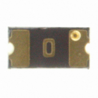
***Features Multifuse
****Features Multifuse
Operating Temperature ......................................... -40 °C to +85 °C
Maximum Device Surface Temperature
in Tripped State .................................................... 125 °C
Passive Aging ....................................................... +85 °C, 1000 hours ............................................... ±5 % typical resistance change
Humidity Aging ..................................................... +85 °C, 85 % R.H. 1000 hours ............................. ±5 % typical resistance change
Thermal Shock ..................................................... +85 °C to -40 °C, 20 times ................................... ±10 % typical resistance change
Solvent Resistance ............................................... MIL-STD-202, Method 215 ................................... No change
Vibration ............................................................... MIL-STD-883C, Method 2007.1, .......................... No change
Test
Visual/Mech. ......................................................... Verify dimensions and materials ........................... Per MF physical description
Resistance ............................................................ In still air @ 23 °C .................................................. Rmin ≤ R ≤ R1max
Time to Trip ........................................................... At specifi ed current, Vmax, 23 °C ........................ T ≤ max. time to trip (seconds)
Hold Current ......................................................... 30 min. at Ihold ..................................................... No trip
Trip Cycle Life ....................................................... Vmax, Imax, 100 cycles ........................................ No arcing or burning
Trip Endurance ..................................................... Vmax, 48 hours ..................................................... No arcing or burning
Solderability .......................................................... ANSI/J-STD-002 ................................................... 95 % min. coverage
UL File Number .................................................... E174545
CSA File Number .................................................. CA110338
TÜV Certifi cate Number ....................................... R 02057213
MF-NSMF012
MF-NSMF020
MF-NSMF020X***
MF-NSMF035
MF-NSMF035X****
MF-NSMF050
MF-NSMF075
MF-NSMF110
MF-NSMF150
MF-NSMF150D
MF-NSMF200
Environmental Characteristics
Test Procedures And Requirements For Model MF-NSMF Series
Electrical Characteristics
Model
®
®
freeXpansion Design
freeXpansion Design
V max.
Volts
30.0
24.0
30.0
16.0
13.2
6.0
6.0
6.0
6.0
6.0
6.0
**To be considered halogen free, each homogenous material can have a maximum concentration of 900 ppm of either bromine or chlorine.
I max.
Amps
100
100
100
100
100
100
100
10
10
60
20
™
™
for MF-NSMF Series (CSA/TÜV pending)
for MF-NSMF Series (CSA pending)
I hold
Hold
0.12
0.20
0.20
0.35
0.35
0.50
0.75
1.10
1.50
1.50
2.00
Condition A
Test Conditions
http://www.ul.com/ Follow link to Certifi cations, then UL File No., enter E174545
http://directories.csa-international.org/ Under “Certifi cation Record” and “File Number”
enter 110338-0-000
http://www.tuvdotcom.com/ Follow link to “other certifi cates”, enter File No. 2057213
Features
■
■
■
■
■
■
MF-NSMF Series - PTC Resettable Fuses
Compact design to save board space -
1206 footprint
Small size results in very fast time to react
to fault events
Symmetrical design
Low profi le
RoHS compliant* and halogen free**
Agency recognition:
Amperes
at 23 °C
0.29
0.46
0.40
0.75
0.75
1.00
1.50
2.20
3.00
3.00
4.00
I trip
Trip
R Min.
1.35
0.60
0.60
0.30
0.30
0.15
0.10
0.06
0.03
0.03
0.02
Resistance
Customers should verify actual device performance in their specifi c applications.
at 23 °C
Ohms
R 1Max.
0.085
8.50
2.60
3.30
1.20
1.40
0.70
0.40
0.20
0.13
0.11
*RoHS Directive 2002/95/EC Jan 27, 2003 including Annex.
Applications
■
■
■
■
■
■
Accept/Reject Criteria
Amperes
USB port protection - USB 2.0, 3.0 & OTG
HDMI 1.4 Source protection
PC motherboards - Plug and Play
protection
Mobile phones - Battery and port protection
PDAs / digital cameras
Game console port protection
at 23 °C
Specifi cations are subject to change without notice.
1.0
1.0
1.0
8.0
3.5
8.0
8.0
8.0
8.0
8.0
8.0
Max. Time
To Trip
Seconds
at 23 °C
0.20
0.60
0.60
0.10
0.14
0.10
0.10
0.10
0.30
0.30
1.00
Dissipation
at 23 °C
Tripped
Power
Watts
Typ.
0.4
0.6
0.6
0.6
0.6
0.4
0.4
0.6
0.6
1.0
0.7


