CMF-SD25-2 Bourns Inc., CMF-SD25-2 Datasheet - Page 2
CMF-SD25-2
Manufacturer Part Number
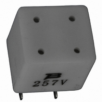
CMF-SD25-2
Description
CPTC FUSE RESET .130A HOLD SMD
Manufacturer
Bourns Inc.
Series
CMF-SDr
Type
Telecom CPTC Resettable Fusesr
Datasheet
1.CMF-SD25-2.pdf
(3 pages)
Specifications of CMF-SD25-2
Voltage - Max
230V
Time To Trip
0.3s
Current - Hold (ih) (max)
130mA
Current - Trip (it)
260mA
Current - Max
2.8A
Package / Case
Non-Standard SMD
Hold Current
0.13 Amp
Trip Current
0.26 Amp
Current Rating (max)
2.8 Amps
Resistance
25 Ohms
Maximum Voltage
230 VoltsAC
Termination Style
SMD/SMT
Mounting Style
SMD/SMT
Dimensions
9 mm L x 10.8 mm W x 10.2 mm H
Lead Free Status / RoHS Status
Lead free / RoHS Compliant
R Min/max
-
Lead Free Status / Rohs Status
Lead free / RoHS Compliant
Other names
CMF-SD25-2TR


Applications
Used as a secondary overcurrent protection
device in:
■
■
■
COPLANARITY:
(Reduced value available on request.)
Packaging Options - Tape and Reel:
CMF-SD10, CMF-SD25, CMF-SD35 & CMF-SD50 = 400
pcs. per reel;
CMF-SD35A & CMF-SD50A = 500 pcs. per reel
Solder refl ow
•
•
•
•
•
Note:
•
Rework
•
DIMENSIONS:
H
Solder Refl ow Recommendations
Product Dimensions
Customer Premise Equipment (CPE)
Central Offi ce (CO)
Access equipment
Recommended refl ow methods: IR, vapor phase oven, hot air oven.
Devices are not designed to be wave soldered to the bottom side of the
board.
Gluing the devices is not recommended.
Recommended maximum paste thickness is 0.25 mm (.010 inch).
Devices can be cleaned using standard industry methods and solvents.
If refl ow temperatures exceed the recommended profi le, devices may not
meet the performance requirements.
A device should not be reworked.
300
250
200
150
100
50
CMF-SD Series - Telecom CPTC Resettable Fuses
0
F
A
(INCHES)
(.006)
0.15
MM
Preheating
160–220
B
G
Time (seconds)
D
E
C
Soldering
10–20
Dim.
G
A
B
C
D
E
H
F
Cooling
120
(.354)
10.80
(.425) MAX.
10.20
(.402)
(.020) MAX.
(.192 - .208)
(.095 - .103)
CMF-SD10
CMF-SD25
CMF-SD35
CMF-SD50
9.00
4.88 - 5.28
2.41 - 2.61
0.5
(.098)
(.039)
2.5
1.0
MAX.
MAX.
CMF-SD35A
CMF-SD50A
(.281) MAX.
(.355)
(.319)
(.020) MAX.
(.128 - .144)
(.095 - .103)
7.15
8.50
8.10
3.25 - 3.65
2.41 - 2.61
0.5
Customers should verify actual device performance in their specifi c applications.
(.098)
(.039)
2.5
1.0
MAX.
MAX.
Recommended Pad Layout
A
Dim.
Specifi cations are subject to change without notice.
1
3
A
B
C
D
G
H
E
F
1
3
CMF-SD SERIES, REV. O, 05/10
DIMENSIONS:
CMF-SD10
CMF-SD25
CMF-SD35
CMF-SD50
(.394)
(.346)
(.126)
(.079)
(.102)
(.197)
(.299)
(.394)
10.0
8.80
3.20
2.00
2.60
5.00
7.60
10.0
B
H
C
2
4
(INCHES)
MM
CMF-SD35A
CMF-SD50A
D
(.315)
(.278)
(.108)
(.079)
(.099)
(.136)
(.234)
(.321)
8.00
7.05
2.75
2.00
2.51
3.45
5.95
8.15
E
F
2
4
G
Related parts for CMF-SD25-2
Image
Part Number
Description
Manufacturer
Datasheet
Request
R

Part Number:
Description:
Cmf-sd Series - Telecom Cptc Resettable Fuses
Manufacturer:
Bourns, Inc.
Datasheet:

Part Number:
Description:
CPTC FUSE RESET .090A HOLD SMD
Manufacturer:
Bourns Inc.
Datasheet:

Part Number:
Description:
CPTC FUSE RESET .100A HOLD SMD
Manufacturer:
Bourns Inc.
Datasheet:

Part Number:
Description:
Ceramic PTC
Manufacturer:
Bourns Inc.
Datasheet:
Part Number:
Description:
Ceramic PTC
Manufacturer:
Bourns Inc.
Datasheet:
Part Number:
Description:
Ceramic PTC
Manufacturer:
Bourns Inc.
Datasheet:
Part Number:
Description:
Ceramic PTC
Manufacturer:
Bourns Inc.
Datasheet:
Part Number:
Description:
Ceramic PTC
Manufacturer:
Bourns Inc.
Datasheet:
Part Number:
Description:
Ceramic PTC
Manufacturer:
Bourns Inc.
Datasheet:
Part Number:
Description:
Ceramic PTC
Manufacturer:
Bourns Inc.
Datasheet:
Part Number:
Description:
Cmf-rlc Series - Telecom Cptc Resettable Fuses
Manufacturer:
Bourns, Inc.
Datasheet:
Part Number:
Description:
Cmf-rd Series - Telecom Cptc Resettable Fuses
Manufacturer:
Bourns, Inc.
Datasheet:
Part Number:
Description:
Cmf-sd Series - Telecom Cptc Resettable Fuses
Manufacturer:
Bourns, Inc.
Datasheet:
Part Number:
Description:
Cmf-rq Series - Telecom Cptc Resettable Fuses
Manufacturer:
Bourns, Inc.
Datasheet: