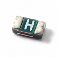
0603L010YR Littelfuse Inc, 0603L010YR Datasheet - Page 3

0603L010YR
Manufacturer Part Number
0603L010YR
Description
PTC RESETTABLE 15V .10A SMD 0603
Manufacturer
Littelfuse Inc
Series
POLYFUSE® 0603Lr
Datasheet
1.0603L020YR.pdf
(5 pages)
Specifications of 0603L010YR
Package / Case
0603 (1608 Metric)
R Min/max
0.900 ~ 6.000 Ohm
Voltage - Max
15V
Time To Trip
1s
Current - Hold (ih) (max)
100mA
Current - Trip (it)
300mA
Current - Max
40A
Hold Current
0.1 Amp
Trip Current
0.3 Amp
Current Rating (max)
40 Amps
Resistance
6 Ohms
Maximum Voltage
15 VoltsDC
Termination Style
SMD/SMT
Mounting Style
SMD/SMT
Holding Current
100mA
Tripping Current
300mA
Initial Resistance Max
6ohm
Operating Voltage
15VDC
Ptc Fuse Case
0603
External Depth
0.75mm
Initial Resistance Min
0.9ohm
Rohs Compliant
Yes
Lead Free Status / RoHS Status
Lead free / RoHS Compliant
Lead Free Status / RoHS Status
Lead free / RoHS Compliant, Lead free / RoHS Compliant
Other names
0603L010
F2900TR
F2900TR
Available stocks
Company
Part Number
Manufacturer
Quantity
Price
Company:
Part Number:
0603L010YR
Manufacturer:
LITTLEFUSE
Quantity:
55 000
© 2010 Littelfuse, Inc
Specifications are subject to change without notice.
Please refer to www.littelfuse.com/series/0603L.html for current information.
Terminal Material
Lead Solderability
Soldering Parameters
Profile Feature
Average Ramp-Up Rate (T
Pre Heat:
Time Maintained
Above:
Peak / Classification Temperature (T
Time within 5°C of actual peak
Temperature (t
Ramp-down Rate
Time 25°C to peak Temperature (T
Physical Specifications
p
)
Temperature Min (T
Temperature Max (T
Time (Min to Max) (t
Temperature (T
Temperature (t
Solder-Plated Copper
(Solder Material: Matte Tin (Sn))
Meets EIA Specification RS186-9E,
ANSI/J-STD-002, Category 3.
S(max)
to T
L
L
)
)
P
P
)
)
P
s(min)
s(max)
)
s
)
)
)
Pb-Free Assembly
3°C/second max
150°C
200°C
60 – 180 secs
217°C
60 – 150 seconds
260
20 – 40 seconds
6°C/second max
8 minutes Max.
Surface Mount > 0603L Series
+0/-5
POLYFUSE
°C
Revised: July 12, 2010
®
17
Resettable PTCs
-- All temperature refer to topside of the package, measured on the package body surface
-- If reflow temperature exceeds the recommended profile, devices may not meet the
-- Recommended reflow methods: IR, vapor phase oven, hot air oven, N
-- Recommended maximum paste thickness is 0.25mm (0.010 inch)
-- Devices can be cleaned using standard industry methods and solvents
-- Devices can be reworked using the standard industry practices
Operating/Storage
Temperature
Maximum Device Surface
Temperature in Tripped State
Passive Aging
Humidity Aging
Thermal Shock
Solvent Resistance
Vibration
Moisture Sensitivity Level
Environmental Specifications
performance requirements
lead
-40°C to +85°C
125°C
+85°C, 1000 hours
-/+10% typical resistance change
+85°C, 85% R.H.,100 hours
-/+15% typical resistance change
MIL–STD–202, Method 107G
+85°C/-40°C 20 times
-30% typical resistance change
MIL–STD–202, Method 215
No change
MIL–STD–883C, Method 2007 .1,
Condition A
No change
Level 1, J–STD–020C
2
environment for
0603L Series


