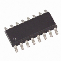
U5020M-MFPG3Y Atmel, U5020M-MFPG3Y Datasheet

U5020M-MFPG3Y
Specifications of U5020M-MFPG3Y
Related parts for U5020M-MFPG3Y
U5020M-MFPG3Y Summary of contents
Page 1
... Enable Output 1. Description The digital window watchdog timer, U5020M CMOS integrated circuit. In applica- tions where safety is critical especially important to monitor the microcontroller. Normal microcontroller operation is indicated by a cyclically transmitted trigger signal, which is received by a window watchdog timer within a defined time window. ...
Page 2
... Figure 1-1. Block Diagram with External Ciruit OSC C 1 Reset 10 Input Micro- controller Trigger Mode 12 3-8 Wake up 2. Pin Configuration Figure 2-1. Pinning SO16 U5020M Oscillator OSC 11 Input signal conditioning Power-on POR reset 14 GND WAKE-UP WAKE-UP 4 WAKE-UP 5 WAKE-UP 6 WAKE- WAKE-UP OSC ...
Page 3
... TS Programming pin to select different time durations for the long watchdog time. 4. Functional Description 4.1 Supply, Pin 13 The U5020M requires a stabilized supply voltage V characteristics. An external buffer capacitor may be connected between pin 13 and GND. 4.2 RC Oscillator, Pin 15 The clock frequency, f, can be adjusted by the components R ...
Page 4
... The switch-over mode time enables the synchronous operation of microcontroller and watchdog. When the power-up reset time has elapsed, the watchdog has to be switched to monitoring mode by the microcontroller by a “low” signal transmitted to the mode pin (pin 12) within the time-out period, t erates a reset pulse, t synchronized with the switchover mode time, t U5020M 4 = 500 ...
Page 5
... The positive edge of the trigger signal , (enable time). The 3 2 Pin 13 Pin Pin 12 Pin ensure correct operation of the micro and an enable time which a trigger sig U5020M 5 ...
Page 6
... The watchdog can be switched back from the long to the short watchdog mode with a low poten- tial at the mode pin (pin 12). Figure 4-5. Pulse Diagram of the Long Watchdog Time Reset out Wake-up Mode Trigger Enable U5020M shows the switch-over from the short to the long watchdog mode. The wake-up signal ...
Page 7
... Parameters Supply voltage Output current Input voltage Ambient temperature range Storage temperature range 7. Thermal Resistance Parameters Junction ambient SO16 4755B–AUTO–11/05 Symbol Value V 6 ±2 OUT V -0 -40 to +85 amb T -55 to +150 stg Symbol Value R 160 thJA U5020M Unit 0 Unit K/W 7 ...
Page 8
... Maximum trigger pulse period Power-up reset time Time-out period Short disable time Short enable time Long disable time Input switch = low (0) Long enable time Input switch = low (0) Long disable time Input switch = high (1) Long enable time Input switch = high (1) Reset-out time U5020M 8 Pin 11, 12 ...
Page 9
... Ordering Information Extended Type Number U5020M-MFPY U5020M-MFPG3Y 10. Package Information Package SO16 Dimensions in mm 11. Revision History Please note that the following page numbers referred to in this section refer to the specific revision mentioned, not to this document. Revision No. 4755B-AUTO-11/05 4755B–AUTO–11/05 Package SO16 SO16 10 ...
Page 10
... Disclaimer: The information in this document is provided in connection with Atmel products. No license, express or implied, by estoppel or otherwise, to any intellectual property right is granted by this document or in connection with the sale of Atmel products. EXCEPT AS SET FORTH IN ATMEL’S TERMS AND CONDI- TIONS OF SALE LOCATED ON ATMEL’S WEB SITE, ATMEL ASSUMES NO LIABILITY WHATSOEVER AND DISCLAIMS ANY EXPRESS, IMPLIED OR STATUTORY WARRANTY RELATING TO ITS PRODUCTS INCLUDING, BUT NOT LIMITED TO, THE IMPLIED WARRANTY OF MERCHANTABILITY, FITNESS FOR A PARTICULAR PURPOSE, OR NON-INFRINGEMENT ...


