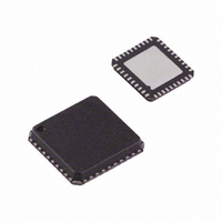
ADM1062ACP-REEL7 Analog Devices Inc, ADM1062ACP-REEL7 Datasheet - Page 23

ADM1062ACP-REEL7
Manufacturer Part Number
ADM1062ACP-REEL7
Description
IC SEQUENCER/SUPERVISOR 40LFCSP
Manufacturer
Analog Devices Inc
Type
Sequencerr
Datasheet
1.EVAL-ADM1062LFEB.pdf
(36 pages)
Specifications of ADM1062ACP-REEL7
Number Of Voltages Monitored
10
Output
Programmable
Voltage - Threshold
Adjustable/Selectable
Operating Temperature
-40°C ~ 85°C
Mounting Type
Surface Mount
Package / Case
40-LFCSP
For Use With
EVAL-ADM1062TQEBZ - BOARD EVALUATION FOR ADM1062TQEVAL-ADM1062LFEBZ - BOARD EVALUATION FOR ADM1062LF
Lead Free Status / RoHS Status
Contains lead / RoHS non-compliant
Reset
-
Reset Timeout
-
TEMPERATURE MEASUREMENT SYSTEM
The ADM1062 contains an on-chip, band gap temperature
sensor whose output is digitized by the on-chip, 12-bit ADC.
Theoretically, the temperature sensor and the ADC can measure
temperatures from −128°C to +128°C with a resolution of 0.125°C.
Because this exceeds the operating temperature range of the device,
local temperature measurements outside this range are not possible.
Temperature measurements from −128°C to +128°C are possible
using a remote sensor. The output code is in offset binary format,
with −128°C given by Code 0x400, 0°C given by Code 0x800,
and +128°C given by Code 0xC00.
As with the other analog inputs to the ADC, a limit register is
provided for each of the temperature input channels. Therefore,
a temperature limit can be set such that if it is exceeded, a warning
is generated and available as an input to the sequencing engine.
This enables users to control their sequence or monitor functions
based on an overtemperature or undertemperature event.
REMOTE TEMPERATURE MEASUREMENT
The ADM1062 can measure the temperature of a remote diode
sensor or diode-connected transistor connected to Pin DN and
Pin DP (Pin 37 and Pin 38 on the LFCSP package and Pin 44
and Pin 45 on the TQFP package).
The forward voltage of a diode or diode-connected transistor
operated at a constant current exhibits a negative temperature
coefficient of about −2 mV/°C. Unfortunately, the absolute value
of V
is required to null it, making the technique unsuitable for mass
production. The technique used in the ADM1062 is to measure
the change in V
currents.
The change in V
where:
k is Boltzmann’s constant.
q is the charge on the carrier.
T is the absolute temperature in Kelvin.
N is the ratio of the two currents.
BE
ΔV
varies from device to device, and individual calibration
BE
= kT/q × ln(N)
BE
BE
when the device is operated at two different
is given by
TRANSISTOR
SENSING
REMOTE
CPU
Figure 36. Signal Conditioning for Remote Diode Temperature Sensors
THERM DA
THERM DC
DP
DN
I
DIODE
BIAS
Rev. B | Page 23 of 36
N × I
I
BIAS
LOW-PASS FILTER
f
V
C
DD
= 65kHz
Figure 36 shows the input signal conditioning used to measure the
output of a remote temperature sensor. This figure shows the
external sensor as a substrate transistor provided for temperature
monitoring on some microprocessors, but it could equally be
a discrete transistor such as a 2N3904 or 2N3906.
If a discrete transistor is used, the collector is not grounded and
should be linked to the base. If a PNP transistor is used, the base
is connected to the DN input, and the emitter is connected to
the DP input. If an NPN transistor is used, the emitter is connected
to the DN input, and the base is connected to the DP input.
Figure 34 and Figure 35 show how to connect the ADM1062 to
an NPN or PNP transistor for temperature measurement. To
prevent ground noise from interfering with the measurement,
the more negative terminal of the sensor is not referenced to
ground but is biased above ground by an internal diode at the
DN input.
Figure 34. Measuring Temperature Using an NPN Transistor
Figure 35. Measuring Temperature Using a PNP Transistor
2N3904
2N3906
NPN
PNP
V
V
OUT+
OUT–
DP
DN
DP
DN
ADM1062
ADM1062
TO ADC
ADM1062


