NJM7924FA NJR, NJM7924FA Datasheet - Page 3
NJM7924FA
Manufacturer Part Number
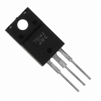
NJM7924FA
Description
IC 24V NEGATIVE REGULATOR TO220F
Manufacturer
NJR
Datasheet
1.NJM7924FA.pdf
(7 pages)
Specifications of NJM7924FA
Regulator Topology
Negative Fixed
Voltage - Output
-24V
Voltage - Input
Down to -40V
Number Of Regulators
1
Current - Output
1.5A
Operating Temperature
-40°C ~ 85°C
Mounting Type
Through Hole
Package / Case
TO-220F
Polarity
Negative
Number Of Outputs
1
Output Type
Fixed
Output Voltage
- 25 V
Output Current
1.5 A
Line Regulation
240 mV
Load Regulation
270 mV
Input Voltage Max
- 40 V
Maximum Operating Temperature
+ 85 C
Minimum Operating Temperature
- 40 C
Maximum Power Dissipation
16000 mW
Mounting Style
Through Hole
Lead Free Status / RoHS Status
Contains lead / RoHS non-compliant
Voltage - Dropout (typical)
-
Current - Limit (min)
-
Lead Free Status / Rohs Status
Lead free / RoHS Compliant


■ ELECTRICAL CHARACTERISTICS (Tj 25ºC, C
Ver.2003-09-24
NJM7905FA
NJM7906FA
NJM7908FA
NJM7909FA
NJM7912FA
Output Voltage
Quiescent Current
Load Regulation
Line Regulation
Ripple Rejection
Output Noise Voltage
Average Temperature
Output Voltage
Quiescent Current
Load Regulation
Line Regulation
Ripple Rejection
Output Noise Voltage
Average Temperature
Output Voltage
Quiescent Current
Load Regulation
Line Regulation
Ripple Rejection
Output Noise Voltage
Average Temperature
Output Voltage
Quiescent Current
Load Regulation
Line Regulation
Ripple Rejection
Output Noise Voltage
Average Temperature
Output Voltage
Quiescent Current
Load Regulation
Line Regulation
Ripple Rejection
Output Noise Voltage
Average Temperature
Coefficient of Output Voltage
Coefficient of Output Voltage
Coefficient of Output Voltage
Coefficient of Output Voltage
Coefficient of Output Voltage
PARAMETER
V
I
∆V
∆V
RR
V
∆V
V
I
∆V
∆V
RR
V
∆V
V
I
∆V
∆V
RR
V
∆V
V
I
∆V
∆V
RR
V
∆V
V
I
∆V
∆V
RR
V
∆V
Q
Q
Q
Q
Q
SYMBOL
O
NO
O
NO
O
NO
O
NO
O
NO
O
O
O
O
O
O
O
O
O
O
O
O
O
O
O
/∆T
/∆T
/∆T
/∆T
/∆T
- V
- V
- V
- V
- V
- I
- I
- I
- I
- I
O
O
O
O
O
IN
IN
IN
IN
IN
V
V
V
V
V
V
V
V
V
V
V
V
V
V
V
V
V
V
V
V
V
V
V
V
V
V
V
V
V
V
V
V
V
V
V
IN
IN
IN
IN
IN
IN
IN
IN
IN
IN
IN
IN
IN
IN
IN
IN
IN
IN
IN
IN
IN
IN
IN
IN
IN
IN
IN
IN
IN
IN
IN
IN
IN
IN
IN
-
-
-
-
-
-
-
-
-
-
-
-
-
-
-
-
-
-
-
-
-
-
-
-
-
-
-
-
-
-
-
-
-
-
-
10V, I
10V, I
10V, I
7 to -25V, I
10V, I
10V, I
10V, I
11V, I
11V, I
11V, I
8 to -25V, I
11V, I
11V, I
11V, I
14V, I
14V, I
14V, I
10.5 to -25V, I
14V, I
14V, I
14V, I
15V, I
15V, I
15V, I
11.5 to -25V, I
15V, I
15V, I
15V, I
19V, I
19V, I
19, V, I
14.5 to -30V, I
19V, I
19V, I
19V, I
O
O
O
O
O
O
O
O
O
O
O
O
O
O
O
O
O
O
O
O
O
O
O
O
O
O
O
O
O
O
0.5A
0mA
0.005 to 1.5A
0.5A, e
0.5A , BW 10Hz to 100kHz
5mA
0.5A
0mA
0.005 to 1.5A
0.5A, e
0.5A , BW 10Hz to 100kHz
5mA
0.5A
0mA
0.005 to 1.5A
0.5A, e
0.5A , BW 10Hz to 100kHz
5mA
0.5A
0mA
0.005 to 1.5A
0.5A, e
0.5A , BW 10Hz to 100kHz
5mA
0.5A
0mA
0.5A, e
0.5A , BW 10Hz to 100kHz
5mA
IN
0.005 to 1.5A
TEST CONDITION
O
O
2.2µF, C
0.5A
0.5A
O
O
O
in
in
in
in
in
0.5A
0.5A
0.5A
2V
2V
2V
2V
2V
P-P
P-P
P-P
P-P
P-P
O
, f 120Hz
, f 120Hz
, f 120Hz
, f 120Hz
, f 120Hz
1.0µF)
Measurement is to be conducted in pulse testing.
-5.75
-8.65
-11.5
MIN.
-4.8
-7.7
-54
54
54
54
54
-
-
-
-
-
-
-
-
-
-
-
-
-
-
-
-
-
-
-
-
-
-
-
-
-12.0
TYP.
-.0.7
-5.0
100
-0.4
-6.0
110
-0.5
-8.0
130
-9.0
150
-0.8
150
-0.4
2.2
2.2
2.2
2.2
2.7
50
60
50
60
60
60
60
59
60
68
5
5
8
8
3
MAX.
-6.25
-9.35
-12.5
-5.2
-8.3
120
150
120
110
5.0
5.0
5.0
5.0
6.0
80
50
90
60
80
90
-
-
-
-
-
-
-
-
-
-
-
-
-
-
mV/ºC
mV/ºC
mV/ºC
mV/ºC
mV/ºC
UNIT
- 3 -
mA
mV
mV
mA
mV
mV
mA
mV
mV
mA
mV
mV
mA
mV
mV
dB
µV
dB
µV
dB
µV
dB
µV
dB
µV
V
V
V
V
V
Related parts for NJM7924FA
Image
Part Number
Description
Manufacturer
Datasheet
Request
R

Part Number:
Description:
IC POS V-REG 3-TERM ADJ TO-252
Manufacturer:
NJR
Datasheet:

Part Number:
Description:
IC REG LDO 800MA 1.8V TO252-5
Manufacturer:
NJR
Datasheet:

Part Number:
Description:
IC REG LDO 800MA 2.3V TO252-5
Manufacturer:
NJR
Datasheet:
Part Number:
Description:
IC LDO VOLT REG 3.0V TO-252
Manufacturer:
NJR
Datasheet:
Part Number:
Description:
IC REG LDO 800MA 5V TO252-5
Manufacturer:
NJR
Datasheet:
Part Number:
Description:
IC REG LDO 800MA 3.3V TO252-5
Manufacturer:
NJR
Datasheet:

Part Number:
Description:
Linear Regulators - Standard 3 T Pos Vs W/Reset
Manufacturer:
NJR

Part Number:
Description:
Linear Regulators - Standard 5V 1.5A 3 Terminal Lead Free Package
Manufacturer:
NJR

Part Number:
Description:
Linear Regulators - Standard -5V .1A 3 Terminal
Manufacturer:
NJR

Part Number:
Description:
Linear Regulators - Standard 3 T Pos Vs W/Reset
Manufacturer:
NJR

Part Number:
Description:
Linear Regulators - Standard 15V .5A 3 Terminal Lead Free Package
Manufacturer:
NJR
Part Number:
Description:
Linear Regulators - Standard 15V .1A 3 Terminal
Manufacturer:
NJR
Part Number:
Description:
Linear Regulators - Standard 18V .1A 3 Terminal Lead Free Package
Manufacturer:
NJR
Part Number:
Description:
Linear Regulators - Standard 6V .5A 3 Terminal
Manufacturer:
NJR