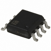
MIC5209-3.6YM Micrel Inc, MIC5209-3.6YM Datasheet - Page 11

MIC5209-3.6YM
Manufacturer Part Number
MIC5209-3.6YM
Description
IC REG LDO 500MA 1% 3.6V 8-SOIC
Manufacturer
Micrel Inc
Datasheet
1.MIC5209-3.3YS_TR.pdf
(13 pages)
Specifications of MIC5209-3.6YM
Regulator Topology
Positive Fixed
Voltage - Output
3.6V
Voltage - Input
Up to 16V
Voltage - Dropout (typical)
0.35V @ 500mA
Number Of Regulators
1
Current - Output
500mA
Operating Temperature
-40°C ~ 125°C
Mounting Type
Surface Mount
Package / Case
8-SOIC (3.9mm Width)
Lead Free Status / RoHS Status
Lead free / RoHS Compliant
Current - Limit (min)
-
Other names
576-2370
MIC5209-3.6YM
MIC5209-3.6YM
Available stocks
Company
Part Number
Manufacturer
Quantity
Price
Company:
Part Number:
MIC5209-3.6YM
Manufacturer:
WINBOND
Quantity:
301
Part Number:
MIC5209-3.6YM
Manufacturer:
MICREL/麦瑞
Quantity:
20 000
Considering worst case tolerances, the power dissipation
could be as high as:
Using the maximum junction temperature of 125°C and a θ
of 8°C/W for the SOT-223, 25°C/W for the SO-8, or 2°C/W
for the TO-263 package, the following worst-case heat-sink
thermal resistance (θ
Table 2 and Figure 6 show that the Slot-1 power supply ap-
plication can be implemented with a minimum footprint layout.
June 2006
T
T
T
T
θ
θ
θ
θ
A
A
A
A
JA
SA
SA
SA
SA
SA
SA
SA
SA
SA
Table 2. Maximum Allowable Thermal Resistance
(limit)
(limit)
SOT-223
SOT-223
SOT-223
SO-8
SO-8
SO-8
TO-263-5
TO-263-5
TO-263-5
(V
[(3.6V – 2.375V) × 320mA] + (3.6V × 4mA)
P
θ
θ
SA
SA
SA
D
JA
IN(max)
= 407mW
= θ
= θ
=
JA
JA
JA
T
T
– V
J(max)
J(max
J(max
= θ
= θ
209°C/W
209°C/W
201°C/W
201°C/W
201°C/W
184°C/W
184°C/W
184°C/W
207°C/W
207°C/W
207°C/W
40°C
40°C
40°C
OUT(max)
JC
P
P
D
D
D
SA
−
) requirements are:
T
T
A
A
A
) × I
184°C/W
184°C/W
176°C/W
176°C/W
176°C/W
159°C/W
159°C/W
159°C/W
182°C/W
182°C/W
182°C/W
50°C
50°C
50°C
OUT
+ V
160°C/W
160°C/W
152°C/W
152°C/W
152°C/W
135°C/W
135°C/W
135°C/W
158°C/W
158°C/W
158°C/W
IN(max)
60°C
60°C
60°C
× I
GND
123°C/W
123°C/W
121°C/W
121°C/W
121°C/W
115°C/W
115°C/W
115°C/W
98°C/W
98°C/W
98°C/W
75°C
75°C
75°C
JC
11
Figure 6 shows the necessary copper pad area to obtain
specifi c heat sink thermal resistance (θ
values in Table 2 require much less than 500mm
according to Figure 6, and can easily be accomplished with
the minimum footprint.
Figure 6. PCB Heat Sink Thermal Resistance
70
60
50
40
30
20
10
0
0
COPPER HEAT SINK AREA (mm
COPPER HEAT SINK AREA (mm
COPPER HEAT SINK AREA (mm )
2000
4000
SA
) values. The θ
6000
2
2
M9999-060906
2
of copper,
SA


