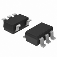
NCP585LSN09T1G ON Semiconductor, NCP585LSN09T1G Datasheet - Page 10

NCP585LSN09T1G
Manufacturer Part Number
NCP585LSN09T1G
Description
IC REG LDO 300MA 0.9V SOT23-5
Manufacturer
ON Semiconductor
Datasheet
1.NCP585DSN12T1G.pdf
(13 pages)
Specifications of NCP585LSN09T1G
Regulator Topology
Positive Fixed
Voltage - Output
0.9V
Voltage - Input
Up to 6V
Voltage - Dropout (typical)
0.55V @ 300mA
Number Of Regulators
1
Current - Output
300mA (Min)
Operating Temperature
-40°C ~ 85°C
Mounting Type
Surface Mount
Package / Case
SOT-23-5, SC-74A, SOT-25
Lead Free Status / RoHS Status
Lead free / RoHS Compliant
Current - Limit (min)
-
Other names
NCP585LSN09T1GOSTR
Available stocks
Company
Part Number
Manufacturer
Quantity
Price
Part Number:
NCP585LSN09T1G
Manufacturer:
ON/安森美
Quantity:
20 000
Input Decoupling
be connected between V
considerations, the traces on V
sufficiently wide in order to minimize noise and prevent
unstable operation.
100000
100000
A 1.0 mF ceramic capacitor is the recommended value to
10000
10000
1000
1000
0.01
0.01
100
100
0.1
0.1
10
10
1
1
0
0
Figure 32. Output Stability, Output Capacitor ESR
Unstable
Unstable
Region
Region
No unstable region in LP Mode
No unstable region in LP Mode
Figure 34. Output Stability, Output Capacitor
ESR vs. Output Load Current (10 mF)
50
50
vs. Output Load Current (0.1 mF)
OUTPUT CURRENT (mA)
OUTPUT CURRENT (mA)
100
100
in
Stable Region
Stable Region
and GND. For PCB layout
150
150
in
and GND should be
200
200
TYPICAL CHARACTERISTICS
APPLICATION INFORMATION
C
V
FT Mode
C
V
FT Mode
out
out
out
out
250
250
= 1.8 V
= 1.8 V
= 0.1 mF
= 10 mF
http://onsemi.com
300
300
10
100000
100000
10000
10000
Output Decoupling
For better performance, select a capacitor with low
Equivalent Series Resistance (ESR). For PCB layout
considerations, place the output capacitor close to the
output pin and keep the leads short as possible.
1000
1000
0.01
0.01
100
100
0.1
0.1
It is best to use a 1.0 mF capacitor value on the V
10
10
1
1
Figure 35. Output Stability, Output Capacitor ESR
0
0
Unstable
Unstable
Region
Region
No unstable region in LP Mode
No unstable region in LP Mode
Figure 33. Output Stability, Output Capacitor
ESR vs. Output Load Current (1.0 mF)
50
50
vs. Output Load Current (100 mF)
OUTPUT CURRENT (mA)
OUTPUT CURRENT (mA)
100
100
Stable Region
Stable Region
150
150
200
200
C
V
FT Mode
C
V
FT Mode
out
out
out
out
250
250
= 1.8 V
= 100 mF
= 1.8 V
= 1.0 mF
out
pin.
300
300


