MCP1827S-3002E/AB Microchip Technology, MCP1827S-3002E/AB Datasheet - Page 20
MCP1827S-3002E/AB
Manufacturer Part Number
MCP1827S-3002E/AB
Description
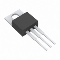
IC REG LDO 1.5A 3.0V TO-220-3
Manufacturer
Microchip Technology
Datasheet
1.MCP1827-ADJEET.pdf
(32 pages)
Specifications of MCP1827S-3002E/AB
Regulator Topology
Positive Fixed
Voltage - Output
3V
Voltage - Input
Up to 6V
Voltage - Dropout (typical)
0.33V @ 1.5A
Number Of Regulators
1
Current - Output
1.5A (Min)
Operating Temperature
-40°C ~ 125°C
Mounting Type
Through Hole
Package / Case
TO-220-3
Primary Input Voltage
3.6V
Output Voltage Fixed
3V
Dropout Voltage Vdo
330mV
No. Of Pins
3
Output Current
1.5A
Operating Temperature Range
-40°C To +125°C
Peak Reflow Compatible (260 C)
Yes
Number Of Outputs
1
Polarity
Positive
Input Voltage Max
6 V
Output Voltage
3 V
Output Type
Fixed
Dropout Voltage (max)
0.6 V at 1.5 A
Line Regulation
0.05 % / V
Load Regulation
0.5 %
Voltage Regulation Accuracy
2 %
Maximum Operating Temperature
+ 125 C
Mounting Style
Through Hole
Minimum Operating Temperature
- 40 C
Lead Free Status / RoHS Status
Lead free / RoHS Compliant
Current - Limit (min)
-
Lead Free Status / Rohs Status
Lead free / RoHS Compliant


MCP1827/MCP1827S
The maximum power dissipation capability for a
package
junction-to-ambient thermal resistance and the maxi-
mum ambient temperature
Equation 5-4 can be used to determine the package
maximum internal power dissipation.
EQUATION 5-4:
EQUATION 5-5:
EQUATION 5-6:
DS22001C-page 20
P
P
T
T
T
T
D(MAX)
D(MAX)
A(MAX)
J(RISE)
J(RISE)
J(MAX)
Rθ
Rθ
T
T
JA
JA
A
J
P
can
D MAX
= Maximum device power dissipation
= maximum continuous junction
= maximum ambient temperature
= Thermal resistance from junction to
= Rise in device junction temperature
= Maximum device power dissipation
= Thermal resistance from junction to
= Junction temperature
= Rise in device junction temperature
= Ambient temperature
T
(
J RISE
(
over the ambient temperature
ambient
over the ambient temperature
temperature
ambient
T
)
J
be
=
)
=
=
(
---------------------------------------------------
T
T
P
J RISE
J MAX
(
(
D MAX
calculated
(
Rθ
)
)
+
–
for the application.
)
JA
T
×
T
A
A MAX
Rθ
(
JA
)
given
)
the
5.3
Internal power dissipation, junction temperature rise,
junction temperature and maximum power dissipation
is calculated in the following example. The power
dissipation as a result of ground current is small
enough to be neglected.
5.3.1
5.3.1.1
The internal junction temperature rise is a function of
internal power dissipation and the thermal resistance
from junction-to-ambient for the application. The
thermal resistance from junction-to-ambient (Rθ
derived from EIA/JEDEC standards for measuring
thermal resistance. The EIA/JEDEC specification is
JESD51. The standard describes the test method and
board specifications for measuring the thermal
resistance from junction to ambient. The actual thermal
resistance for a particular application can vary
depending on many factors such as copper area and
thickness. Refer to AN792, “A Method to Determine
How Much Power a SOT23 Can Dissipate in an
Application” (DS00792), for more information regarding
this subject.
Package
Input Voltage
LDO Output Voltage and Current
Maximum Ambient Temperature
Internal Power Dissipation
Package Type = TO-220-5
P
T
LDO(MAX)
T
T
J(RISE)
T
JRISE
JRISE
A(MAX)
Typical Application
V
P
P
I
OUT
OUT
LDO
LDO
POWER DISSIPATION EXAMPLE
V
IN
Device Junction Temperature Rise
= P
= 1.54 W x 29.3
= 45.12
= 3.3V ± 5%
= 2.5V
= 1.5A
= 60°C
= (V
= ((3.3V x 1.05) – (2.5V x 0.975))
= 1.54 Watts
TOTAL
x 1.5A
IN(MAX)
°
C
©
x Rθ
2007 Microchip Technology Inc.
– V
JA
°
OUT(MIN)
C/W
) x I
OUT(MAX)
JA
) is
Related parts for MCP1827S-3002E/AB
Image
Part Number
Description
Manufacturer
Datasheet
Request
R

Part Number:
Description:
IC, LDO VOLT REG, 3.3V, 1.5A, D2-PAK-3
Manufacturer:
Microchip Technology
Datasheet:
Part Number:
Description:
IC, LDO VOLT REG, 3V, 1.5A, D2-PAK-3
Manufacturer:
Microchip Technology
Datasheet:
Part Number:
Description:
IC, LDO VOLT REG, 1.8V, 1.5A, D2-PAK-3
Manufacturer:
Microchip Technology
Datasheet:
Part Number:
Description:
IC, LDO VOLT REG, 5V, 1.5A, D2-PAK-3
Manufacturer:
Microchip Technology
Datasheet:
Part Number:
Description:
IC, LDO REG, 1.5A, 1.2V, 3-D2-PAK
Manufacturer:
Microchip Technology
Datasheet:
Part Number:
Description:
IC, LDO REG, 1.5A, 2.5V, 3-D2-PAK
Manufacturer:
Microchip Technology
Datasheet:

Part Number:
Description:
IC REG LDO 1.5A 1.2V TO-220-3
Manufacturer:
Microchip Technology
Datasheet:
Part Number:
Description:
IC REG LDO 1.5A 3.3V TO-220-3
Manufacturer:
Microchip Technology
Datasheet:
Part Number:
Description:
IC REG LDO 1.5A 2.5V TO-220-3
Manufacturer:
Microchip Technology
Datasheet:
Part Number:
Description:
IC REG LDO 1.5A 5.0V TO-220-3
Manufacturer:
Microchip Technology
Datasheet:
Part Number:
Description:
IC REG LDO 1.5A 1.8V TO-220-3
Manufacturer:
Microchip Technology
Datasheet:
Part Number:
Description:
1.5A CMOS LDO, Vout=0.8V, Extended Temp Range 3 DDPAK 3.90mm (.150") TUBE
Manufacturer:
Microchip Technology
Datasheet:
Part Number:
Description:
1.5A CMOS LDO, Vout=0.8V, Extended Temp Range 3 TO-220 3.90mm (.150") TUBE
Manufacturer:
Microchip Technology
Datasheet:
