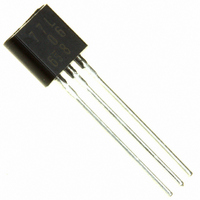
AN77L06 Panasonic - SSG, AN77L06 Datasheet - Page 11

AN77L06
Manufacturer Part Number
AN77L06
Description
VOLTAGE REG POS 6V 100MA TO-92
Manufacturer
Panasonic - SSG
Datasheet
1.AN77L09.pdf
(12 pages)
Specifications of AN77L06
Regulator Topology
Positive Fixed
Voltage - Output
6V
Voltage - Input
Up to 30V
Number Of Regulators
1
Current - Output
100mA
Operating Temperature
-30°C ~ 125°C
Mounting Type
Through Hole
Package / Case
TO-92-3 (Standard Body), TO-226
Lead Free Status / RoHS Status
Lead free / RoHS Compliant
Voltage - Dropout (typical)
-
Current - Limit (min)
-
AN77L05
1. Input short-circuit protection circuit
2. Short-circuit between the output pin and the GND pin
3. Capacitor for external compensation
Usage Notes
with GND pin (pin 3) in the normal operation condition, the potential of output pin (pin 2) becomes higher than that of DC input pin
and the electric charges which is charged in output capacitor C
elements.
current, is incorporated in the internal circuit, the protection diode is not required.
shown in "Figure 3". When your use under a high voltage happens to cause any short-circuit between the output pin (pin 2) and the
GND pin (pin 3), the IC is likely to be broken.
(pin 2) and GND pin (pin 3) as possible. When it is used under low temperature, oscillation may occur due to the decrease of the
aluminum electrolytic capacitor's capacitance and an increase of ESR. For the AN77Lxx series, it is recommended that the tantalum
capacitor or aluminum electrolytic capacitor whose equivalent serial resistance with temperature characteristics within the
recommended range specified in “Figure 2" should be used.
For the conventional Matsushita 3-pin regulators (such as of the AN80xx series), when DC input pin (pin 1) is short-circuited
In the above case, the common silicon diode is connected as shown in the following figure (the dotted line).
However, for the AN77Lxx/AN77LxxM series, since the protection circuit, which protects the elements from the discharging
Because there is no in-built protection circuit in the AN77Lxx/AN77LxxM series, they have the drooping characteristics as
In order to secure the stability, the capacitor of 10 F is required in the output side and it should be added as near to output pin
Figure 1. Protection diode
50
40
30
20
10
0
Figure 2. ESR recommended range
Recommended range
20
Output current I
40
60
V
OUT
IN
(mA)
80
0.33 F
C
IN
1
100
Input
SFF00025AEB
OUT
flows in the input side, having resulted in the breakage of
V
OUT
3
0
Common
Figure 3. Over current limit control
Not required
2
Output
10 F
C
OUT
200
I
OUT
(mA)
11


