AP7173-SPG-13 Diodes Inc, AP7173-SPG-13 Datasheet - Page 11
AP7173-SPG-13
Manufacturer Part Number
AP7173-SPG-13
Description
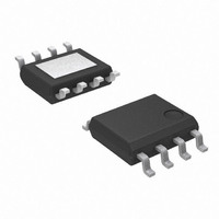
IC REG LDO ADJ 1.5A 8SOIC
Manufacturer
Diodes Inc
Datasheet
1.AP7173-SPG-13.pdf
(15 pages)
Specifications of AP7173-SPG-13
Regulator Topology
Positive Adjustable
Voltage - Output
0.8 ~ 3.3 V
Voltage - Input
1 ~ 5.5 V
Voltage - Dropout (typical)
0.165V @ 1.5A
Number Of Regulators
1
Current - Output
1.5A (Max)
Current - Limit (min)
2A
Operating Temperature
-40°C ~ 85°C
Mounting Type
Surface Mount
Package / Case
8-SOIC (3.9mm Width) Exposed Pad, 8-eSOIC. 8-HSOIC
Lead Free Status / RoHS Status
Lead free / RoHS Compliant
Other names
AP7173-SPG-13
AP7173-SPG-13DITR
AP7173-SPG-13DITR
Available stocks
Company
Part Number
Manufacturer
Quantity
Price

Part Number:
AP7173-SPG-13
Manufacturer:
DIODES/美台
Quantity:
20 000
Company:
Part Number:
AP7173-SPG-13-80
Manufacturer:
CENTRAL
Quantity:
15 362


Application Notes
PROGRAMMABLE SOFT-START (cont.)
The relationship between the soft-start time and the soft-
start charging current (I
and the internal reference voltage (V
Refer to Table 2 for suggested soft-start capacitor values
ENABLE/SHUTDOWN
The EN pin can be used with standard digital signals or
relatively slow-ramping analog signals. Pulling the V
below 0.4V turns the regulator off, while driving the V
above 1.1V turns the regulator on. Figure 30 shows an
example where an RC circuit is used to delay start the
AP7173.
If not used, the EN pin can be connected to the VCC or IN
pin when the V
decoupling measures are taken for the EN pin.
POWER-GOOD
The power-good (PG) pin is an open-drain output and can
be pulled up through a resistor of 10kΩ to1MΩ to V
or any other rail that is 5.5V or lower. When the V
V
V
disabled, the PG pin is pulled to low by an internal
MOSFET.
OVER-CURRENT AND SHORT-CIRCUIT
PROTECTION
The AP7173 features a factory-trimmed, temperature and
supply voltage compensated internal current limit and an
AP7173
Document number: DS31369 Rev. 9 - 2
PG,TH
OUT
drops to below V
+V
PG,HYS
, the PG output is high-impedance; if the
IN
t
SS
is greater than 1.1V, as long as good
Figure 30. Delayed Start Using an RC
Circuit to Enable AP7173
= (V
PG,TH
SS
REF
(Continued)
), soft-start capacitance (C
, V
x C
VCC
SS
≤ 1.9V or the device is
) / I
REF
SS
) is
IN
, V
OUT
SS
www.diodes.com
1.5A LOW DROPOUT LINEAR REGULATOR WITH
OUT
),
EN
EN
≥
1 of 15
over-current protection circuitry to protect the device
against overload conditions. It limits the device current to
a typical value of 3A and reduces the V
tries to pull more current.
For more effective protection against short-circuit failure,
the AP7173 also includes a short-circuit foldback
mechanism that lowers the current limit to a typical value
of 1.0A when the V
THERMAL PROTECTION
Thermal
temperature and protects the device from damage as a
result of overheating.
Thermal protection turns off the V
junction temperature rises to approximately +150°C,
allowing it to cool down. When the junction temperature
drops to approximately +130°C, the output is re-enabled.
Therefore, the thermal protection circuit may cycle on
and off at a rate dependent on the power dissipation,
thermal resistance, and ambient temperature.
POWER DISSIPATION
Thermal shutdown is intented to protect the AP7173
against abnormal overheating. For normal operation,
excessive power dissipation should be avoided and good
heatsinking should be provided. Power dissipation in the
device is the product of the device dropout voltage and
the load current,
As can be seen, power dissipation can be minimized by
using the lowest input voltage necessary to achieve the
required output voltage regulation.
To ensure that the device junction temperature does not
exceed the specified limit of 125°C, an application should
provide heat conduction paths that have junction-to-
ambient thermal resistance lower than the calculated
value here:
For the DFN package with exposed pad, the primary
conduction path for heat is through the exposed pad to
the printed circuit board (PCB). The pad should be
attached to an appropriate amount of copper PCB area to
ensure that the device does not overheat.
shutdown
PROGRAMMABLE SOFT-START
R
P
θJA
D
FB
= (V
drops to below 0.2V.
= (125°C –T
limits
IN
- V
OUT
the
) x I
OUT
A
) / P
OUT
when the AP7173’s
AP7173
OUT
D
AP7173
© Diodes Incorporated
when the load
April 2011
junction
Related parts for AP7173-SPG-13
Image
Part Number
Description
Manufacturer
Datasheet
Request
R

Part Number:
Description:
IC REG LDO ADJ 1.5A 10DFN
Manufacturer:
Diodes Inc
Datasheet:

Part Number:
Description:
Diodes (General Purpose, Power, Switching) 240V 350mW
Manufacturer:
Diodes Inc
Datasheet:

Part Number:
Description:
Diodes (General Purpose, Power, Switching) -
Manufacturer:
Diodes Inc
Part Number:
Description:
Diodes (General Purpose, Power, Switching) -
Manufacturer:
Diodes Inc

Part Number:
Description:
Diodes (General Purpose, Power, Switching) NPN Small SIG 50V 45V VCEO 6.0V VEBO
Manufacturer:
Diodes Inc
Datasheet:
Part Number:
Description:
Diodes (General Purpose, Power, Switching) NPN Small SIG 30V 30V VCEO 5.0V VEBO
Manufacturer:
Diodes Inc
Datasheet:
Part Number:
Description:
Diodes (General Purpose, Power, Switching) NPN Small SIG -80V -65V VCEO -5.0 VEBO
Manufacturer:
Diodes Inc
Datasheet:
Part Number:
Description:
Diodes (General Purpose, Power, Switching) NPN Small SIG -50V -45V VCEO 6.0V VEBO
Manufacturer:
Diodes Inc
Part Number:
Description:
Diodes (General Purpose, Power, Switching) Dual Switching DIODE 100V Vrm 75Vrrm 53Vr
Manufacturer:
Diodes Inc
Datasheet:

Part Number:
Description:
Diodes (General Purpose, Power, Switching) Vr/80V Io/125mA T/R
Manufacturer:
Diodes Inc
Datasheet:

Part Number:
Description:
Diodes (General Purpose, Power, Switching) HV DUAL SW DIODE 300V
Manufacturer:
Diodes Inc
Datasheet:

Part Number:
Description:
Diodes (General Purpose, Power, Switching) 80V 150mW
Manufacturer:
Diodes Inc
Datasheet:
Part Number:
Description:
Diodes (General Purpose, Power, Switching) 75V 150mW
Manufacturer:
Diodes Inc
Datasheet:

Part Number:
Description:
Diodes (General Purpose, Power, Switching) 200MW 80V
Manufacturer:
Diodes Inc
Part Number:
Description:
Diodes (General Purpose, Power, Switching) 100V Io/150mA T/R INVALID P/N
Manufacturer:
Diodes Inc