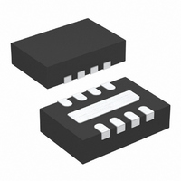
LT3020EDD-1.8#PBF Linear Technology, LT3020EDD-1.8#PBF Datasheet - Page 9

LT3020EDD-1.8#PBF
Manufacturer Part Number
LT3020EDD-1.8#PBF
Description
IC REG LDO 1.8V 100MA LV 8-DFN
Manufacturer
Linear Technology
Datasheet
1.LT3020EDDPBF.pdf
(16 pages)
Specifications of LT3020EDD-1.8#PBF
Regulator Topology
Positive Fixed
Voltage - Output
1.8V
Voltage - Input
Up to 10V
Voltage - Dropout (typical)
0.15V @ 100mA
Number Of Regulators
1
Current - Output
100mA
Current - Limit (min)
110mA
Operating Temperature
-40°C ~ 125°C
Mounting Type
Surface Mount
Package / Case
8-DFN
Lead Free Status / RoHS Status
Lead free / RoHS Compliant
Available stocks
Company
Part Number
Manufacturer
Quantity
Price
BLOCK DIAGRA
APPLICATIO S I FOR ATIO
The LT3020 is a very low dropout linear regulator capable
of 0.9V input supply operation. Devices supply 100mA of
output current and dropout voltage is typically 150mV.
Quiescent current is typically 120µA and drops to 3µA in
shutdown. The LT3020 incorporates several protection
features, making it ideal for use in battery-powered sys-
tems. The device protects itself against reverse-input and
reverse-output voltages. In battery backup applications
where the output is held up by a backup battery when the
input is pulled to ground, the LT3020 acts as if a diode is
in series with its output which prevents reverse current
flow. In dual supply applications where the regulator load
is returned to a negative supply, the output can be pulled
below ground by as much as 10V without affecting start-
up or normal operation.
Adjustable Operation
The LT3020’s output voltage range is 0.2V to 9.5V. Figure
1 shows that the output voltage is set by the ratio of two
external resistors. The device regulates the output to
maintain the ADJ pin voltage at 200mV referenced to
ground. The current in R1 equals 200mV/R1 and the
SHDN
(5)
NOTE:
FOR LT3020 ADJUST PIN 3 IS CONNECTED TO
THE ADJUST PIN, R1 AND R2 ARE EXTERNAL.
FOR LT3020-1.X PIN 3 IS CONNECTED TO THE
OUTPUT SENSE PIN, R1 AND R2 ARE INTERNAL.
BIAS CURRENT
U
GENERATOR
REFERENCE
AND
SHUTDOWN
U
W
200mV
212mV
W
RECOVERY
–
ERROR AMP
+
–
+
NO-LOAD
SHUTDOWN
U
THERMAL
FIXED
V
1.2V
1.5V
1.8V
current in R2 is the current in R1 minus the ADJ pin bias
current. The ADJ pin bias current of 20nA flows out of the
pin. Use the formula in Figure 1 to calculate output voltage.
An R1 value of 20k sets the resistor divider current to
10µA. Note that in shutdown the output is turned off and
the divider current is zero. Curves of ADJ Pin Voltage vs
Temperature and ADJ Pin Bias Current vs Temperature
appear in the Typical Performance Characteristics section.
Specifications for output voltages greater than 200mV are
proportional to the ratio of desired output voltage to
200mV; (V
OUT
CURRENT
GAIN
20k
20k
20k
R1
100k
130k
160k
R2
OUT
/200mV). For example, load regulation for
Figure 1. Adjustable Operation
LT3020-1.5/LT3020-1.8
Q1
Q2
V
R3
IN
D1
V
V
I
OUTPUT RANGE = 0.2V TO 9.5V
ADJ
OUT
ADJ
LT3020/LT3020-1.2/
= 20nA AT 25°C
D2
= 200mV
= 200mV
IN
SHDN
LT3020-ADJ
GND
( )
1 +
Q3
R2
R1
3020 BD
R2
R1
25k
OUT
ADJ
– I
ADJ
(R2)
R2
R1
3020 F01
ADJ
(3)
IN
(7, 8)
OUT
(1, 2)
OUT SENSE
(3)
GND
(4,9)
+
V
OUT
3020fc
9


