AP1184K5-33L-U Diodes Inc, AP1184K5-33L-U Datasheet - Page 5
AP1184K5-33L-U
Manufacturer Part Number
AP1184K5-33L-U
Description
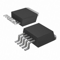
IC REG LDO 4A 3.3V TO263-5
Manufacturer
Diodes Inc
Datasheet
1.AP1184K5-33L-13.pdf
(12 pages)
Specifications of AP1184K5-33L-U
Regulator Topology
Positive Fixed
Voltage - Output
3.3V
Voltage - Input
Up to 16V
Voltage - Dropout (typical)
0.7V @ 4A
Number Of Regulators
1
Current - Output
4A
Current - Limit (min)
4.2A
Operating Temperature
0°C ~ 125°C
Mounting Type
Surface Mount
Package / Case
TO-263-5, D²Pak (5 leads + Tab), TO-263BA
Number Of Outputs
1
Polarity
Positive
Input Voltage Max
16 V
Output Voltage
3.3 V
Output Type
Fixed
Dropout Voltage (max)
0.38 V at 1500 mA
Output Current
4 A
Line Regulation
0.2 %
Load Regulation
33 mV
Maximum Power Dissipation
4.4 W
Maximum Operating Temperature
+ 125 C
Mounting Style
SMD/SMT
Minimum Operating Temperature
0 C
Lead Free Status / RoHS Status
Lead free / RoHS Compliant


Electrical Characteristics
Unless otherwise specified, these specifications apply over, C
V
Notes:
TO263-5L/TO220-5L
Functional Descriptions
Introduction
The AP1184 regulator is a 5 terminal device designed specifically to provide extremely low dropout voltages comparable to the PNP type
without the disadvantage of the extra power dissipation due to the base current associated with PNP regulators. This is done by bringing
out the control pin of the regulator that provides the base current to the power NPN and connecting it to a voltage that is greater than the
voltage present at the
motherboard with an ATX style power supply that provides 5V and 3.3V to the board. One such application is the new graphic chip sets
that require anywhere from 2.4V to 2.7V supply. The AP1184 can easily be programmed with the addition of two external resistors to any
voltages within the range of 1.25V to 15.5V. Another major requirement of these graphic chips is the need to switch the load current from
zero to several amps in tens of nanoseconds at the processor pins, which translates to an approximately 300 to 500ns of current step at
the regulator. In addition, the output voltage tolerances are also extremely tight and they include the transient response as part of the
specification.
The AP1184 is specifically designed to meet the fast current transient needs as well as providing an accurate initial voltage, reducing the
overall system cost with the need for fewer number of output capacitors. Another feature of the device is its true remote sensing capability
that allows accurate voltage setting at the load rather than at the device.
Output Voltage Setting
The AP1184-ADJ can be programmed to any voltages in the range of 1.25V to 15.5V with the addition of R1 and R2 external resistors
according to the following formula:
AP1184 Rev. 5
Sym.
ou
θ
θ
I
adj
JA
JC
t
= V
Adjust Pin Current
Thermal Resistance
Junction-to-Ambient
Thermal Resistance
Junction-to-Case
sense
3. AP1184-ADJ incorporates an internal thermal shutdown that protects the device when the junction temperature exceeds the allowable
4. Test conditions for TO263-5L : Devise mounted on 2oz copper, minimum recommended pad layout , FR-4 PCB.
5. Test conditions for TO220-5L : with copper area of approximately 3in
Package
maximum junction temperature.
Parameter
.
V
in
pin. This flexibility makes the AP1184 ideal for applications where dual inputs are available such as a computer
V
TO263-5L: Control Circuitry/Power Transistor (Note 4)
TO220-5L: Control Circuitry/Power Transistor (Note 5)
TO263-5L: Control Circuitry/Power Transistor (Note 4)
TO220-5L: Control Circuitry/Power Transistor (Note 5)
ctrl
2.4W~4.4W
Max Pd.
= 2.75V, V
4A ULTRA LOW DROPOUT POSITIVE ADJUSTABLE OR
in
(Continued)
= 2.05,V
With heat sink or amount of copper board needed.
www.diodes.com
Test Condition
in
5 of 12
adjj
= 1uF, C
= 0
out
2
, 1oz.
= 10uF, and T
j
Remarks
= 0 to 150
FIXED-MODE REGULATOR
o
C. Typical value refer to T
Min Typ.
SEPTEMBER 2008
50
61
31
©
7
5
AP1184
Diodes Incorporated
Max
150
A
= 25
O
O
O
O
Unit
C/W
C/W
C/W
C/W
µA
o
C.
Related parts for AP1184K5-33L-U
Image
Part Number
Description
Manufacturer
Datasheet
Request
R

Part Number:
Description:
IC REG LDO 4.0A 3.3V TO263-5L
Manufacturer:
Diodes Inc
Datasheet:
Part Number:
Description:
IC REG LDO 4.0A ADJ V TO263-5L
Manufacturer:
Diodes Inc
Datasheet:
Part Number:
Description:
IC REG LDO 4.0A 1.5V TO263-5L
Manufacturer:
Diodes Inc
Datasheet:
Part Number:
Description:
IC REG LDO 4A 1.5V TO263-5
Manufacturer:
Diodes Inc
Datasheet:
Part Number:
Description:
IC REG LDO 4A 1.8V TO263-5
Manufacturer:
Diodes Inc
Datasheet:
Part Number:
Description:
IC REG LDO 4.0A 2.5V TO263-5L
Manufacturer:
Diodes Inc
Datasheet:
Part Number:
Description:
IC REG LDO 4A 2.5V TO263-5
Manufacturer:
Diodes Inc
Datasheet:
Part Number:
Description:
IC REG LDO 4A 5.0V TO263-5
Manufacturer:
Diodes Inc
Datasheet:
Part Number:
Description:
IC REG LDO 4A ADJ TO263-5
Manufacturer:
Diodes Inc
Datasheet:

Part Number:
Description:
Low Dropout (LDO) Regulators LDO BI 4.0A 0.7V 16-18V 1.5V 5.0V FIX
Manufacturer:
Diodes Inc
Datasheet:
Part Number:
Description:
Low Dropout (LDO) Regulators LDO BI 4.0A 0.7V 16-18V 1.5V 1.8V FIX
Manufacturer:
Diodes Inc

Part Number:
Description:
4A Ultra Low Dropout Positive Adjustable or Fixed-mode Regulator
Manufacturer:
ANACHIP [Anachip Corp]
Datasheet:

Part Number:
Description:
Diodes (General Purpose, Power, Switching) 240V 350mW
Manufacturer:
Diodes Inc
Datasheet:

Part Number:
Description:
Diodes (General Purpose, Power, Switching) -
Manufacturer:
Diodes Inc
Part Number:
Description:
Diodes (General Purpose, Power, Switching) -
Manufacturer:
Diodes Inc