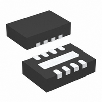
LT3020EDD-1.8#TRPBF Linear Technology, LT3020EDD-1.8#TRPBF Datasheet - Page 13

LT3020EDD-1.8#TRPBF
Manufacturer Part Number
LT3020EDD-1.8#TRPBF
Description
IC REG LDO 1.8V 100MA LV 8-DFN
Manufacturer
Linear Technology
Datasheet
1.LT3020EDDPBF.pdf
(16 pages)
Specifications of LT3020EDD-1.8#TRPBF
Regulator Topology
Positive Fixed
Voltage - Output
1.8V
Voltage - Input
Up to 10V
Voltage - Dropout (typical)
0.15V @ 100mA
Number Of Regulators
1
Current - Output
100mA
Current - Limit (min)
110mA
Operating Temperature
-40°C ~ 125°C
Mounting Type
Surface Mount
Package / Case
8-DFN
Lead Free Status / RoHS Status
Lead free / RoHS Compliant
Available stocks
Company
Part Number
Manufacturer
Quantity
Price
APPLICATIO S I FOR ATIO
and the output voltage clamps at a Schottky diode above
ground. Please note that the behavior described above
applies to the LT3020 only. If a resistor divider is con-
nected under the same conditions, there will be additional
V/R current.
In circuits where a backup battery is required, several
different input/output conditions can occur. The output
voltage may be held up while the input is either pulled to
ground, pulled to some intermediate voltage or is left open
circuit. In the case where the input is grounded, there is
less than 1µA of reverse output current.
If the LT3020 IN pin is forced below the OUT pin or the OUT
pin is pulled above the IN pin, input current drops to less
than 10µA typically. This occurs if the LT3020 input is
connected to a discharged (low voltage) battery and either
a backup battery or a second regulator circuit holds up the
output. The state of the SHDN pin has no effect on the
reverse output current if OUT is pulled above IN.
Input Capacitance and Stability
The LT3020 is designed to be stable with a minimum
capacitance of 2.2µF placed at the IN pin. Ceramic capaci-
tors with very low ESR may be used. However, in cases
where a long wire is used to connect a power supply to the
input of the LT3020 (and also from the ground of the
LT3020 back to the power supply ground), use of low
value input capacitors combined with an output load
current of 20mA or greater may result in an unstable
application. This is due to the inductance of the wire
forming an LC tank circuit with the input capacitor and not
a result of the LT3020 being unstable.
The self-inductance, or isolated inductance, of a wire is
directly proportional to its length. However, the diameter
U
U
W
U
of a wire does not have a major influence on its self-
inductance. For example, the self inductance of a 2-AWG
isolated wire with a diameter of 0.26 in. is about half the
inductance of a 30-AWG wire with a diameter of 0.01 in.
One foot of 30-AWG wire has 465nH of self inductance.
The overall self-inductance of a wire can be reduced in two
ways. One is to divide the current flowing towards the
LT3020 between two parallel conductors. In this case, the
farther the wires are placed apart from each other, the
more inductance will be reduced, up to a 50% reduction
when placed a few inches apart. Splitting the wires basi-
cally connects two equal inductors in parallel. However,
when placed in close proximity from each other, mutual
inductance is added to the overall self inductance of the
wires. The most effective way to reduce overall inductance
is to place the forward and return-current conductors (the
wire for the input and the wire for ground) in very close
proximity. Two 30-AWG wires separated by 0.02 in. re-
duce the overall self-inductance to about one-fifth of a
single isolated wire.
If the LT3020 is powered by a battery mounted in close
proximity on the same circuit board, a 2.2µF input capaci-
tor is sufficient for stability. However, if the LT3020 is
powered by a distant supply, use a larger value input
capacitor following the guideline of roughly 1µF (in addi-
tion to the 2.2µF minimum) per 8 inches of wire length. As
power supply output impedance may vary, the minimum
input capacitance needed to stabilize the application may
also vary. Extra capacitance may also be placed directly on
the output of the power supply; however, this will require
an order of magnitude more capacitance as opposed to
placing extra capacitance in close proximity to the LT3020.
Furthermore, series resistance may be placed between the
supply and the input of the LT3020 to stabilize the appli-
cation; as little as 0.1Ω to 0.5Ω will suffice.
LT3020-1.5/LT3020-1.8
LT3020/LT3020-1.2/
13
3020fc


