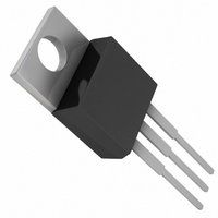
LT1585ACT#PBF Linear Technology, LT1585ACT#PBF Datasheet - Page 8

LT1585ACT#PBF
Manufacturer Part Number
LT1585ACT#PBF
Description
IC LDO REG 5A ADJ TO220-3
Manufacturer
Linear Technology
Datasheet
1.LT1585ACT-3.3PBF.pdf
(12 pages)
Specifications of LT1585ACT#PBF
Regulator Topology
Positive Adjustable
Voltage - Output
1.25 ~ 5.5 V
Voltage - Input
2.45 ~ 7 V
Voltage - Dropout (typical)
1.2V @ 5A
Number Of Regulators
1
Current - Limit (min)
5A
Operating Temperature
0°C ~ 125°C
Mounting Type
Through Hole
Package / Case
TO-220-3 (Straight Leads)
Lead Free Status / RoHS Status
Lead free / RoHS Compliant
Current - Output
-
Available stocks
Company
Part Number
Manufacturer
Quantity
Price
APPLICATIONS
LT1585A/LT1585A-3.3
Load Regulation
It is not possible to provide true remote load sensing
because the LT1585A/LT1585A-3.3 are 3-terminal de-
vices. Load regulation is limited by the resistance of the
wire connecting the regulators to the load. Load regula-
tion per the data sheet specification is measured at the
bottom of the package.
For fixed voltage devices, negative side sensing is a true
Kelvin connection with the ground pin of the device
returned to the negative side of the load. This is illustrated
in Figure 4.
For adjustable voltage devices, negative side sensing is a
true Kelvin connection with the bottom of the output
divider returned to the negative side of the load. The best
8
U
INFORMATION
U
W
V
Figure 4. Connection for Best Load Regulation
V
IN
IN
*CONNECT R1 TO CASE
Figure 5. Connection for Best Load Regulation
CONNECT R2 TO LOAD
IN
IN
LT1585A-3.3
U
GND
LT1585A
ADJ
OUT
OUT
LINE RESISTANCE
PARASITIC
LINE RESISTANCE
load regulation is obtained when the top of resistor divider
R1 connects directly to the regulator output and not to the
load. Figure 5 illustrates this point. If R1 connects to the
load, the effective resistance between the regulator and
the load is:
The connection shown in Figure 5 does not multiply R
the divider ratio. As an example, R
per foot with 16-gauge wire. This translates to 4mV per
foot at 1A load current. At higher load currents, this drop
represents a significant percentage of the overall regula-
tion. It is important to keep the positive lead between the
regulator and the load as short as possible and to use large
wire or PC board traces.
R
PARASITIC
P
R
R2*
R1*
P
R
P
(1 + R2/R1), R
LT1585A • F04
LT1585A • F05
R
R
L
L
P
= Parasitic Line Resistance
P
is about four milliohms
1585afa
P
by


