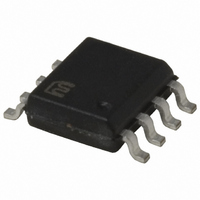
MIC5236YM TR Micrel Inc, MIC5236YM TR Datasheet - Page 9

MIC5236YM TR
Manufacturer Part Number
MIC5236YM TR
Description
IC REG LDO 150MA ADJ VOLT 8-SOIC
Manufacturer
Micrel Inc
Datasheet
1.MIC5236YM.pdf
(12 pages)
Specifications of MIC5236YM TR
Regulator Topology
Positive Adjustable
Voltage - Output
1.24 ~ 20 V
Voltage - Input
2.3 ~ 30 V
Voltage - Dropout (typical)
0.3V @ 150mA
Number Of Regulators
1
Current - Output
150mA
Operating Temperature
-40°C ~ 125°C
Mounting Type
Surface Mount
Package / Case
8-SOIC (3.9mm Width)
Lead Free Status / RoHS Status
Lead free / RoHS Compliant
Current - Limit (min)
-
Other names
MIC5236YMTR
MIC5236YMTR
MIC5236YMTR
Application Information
The MIC5236 provides all of the advantages of the MIC2950:
wide input voltage range, load dump (positive transients up
to 60V), and reversed-battery protection, with the added ad-
vantages of reduced quiescent current and smaller package.
Additionally, when disabled, quiescent current is reduced to
0.1µA.
Enable
A low on the enable pin disables the part, forcing the quies-
cent current to less than 0.1µA. Thermal shutdown and the
error flag are not functional while the device is disabled. The
maximum enable bias current is 2µA for a 2.0V input. An open
collector pull-up resistor tied to the input voltage should be
set low enough to maintain 2V on the enable input. Figure 1
shows an open collector output driving the enable pin through
a 200k pull-up resistor tied to the input voltage.
In order to avoid output oscillations, slow transitions from low
to high should be avoided.
Input Capacitor
An input capacitor may be required when the device is not
near the source power supply or when supplied by a bat-
tery. Small, surface mount, ceramic capacitors can be used
for bypassing. Larger values may be required if the source
supply has high ripple.
Output Capacitor
The MIC5236 has been designed to minimize the effect of the
output capacitor ESR on the closed loop stability. As a result,
ceramic or film capacitors can be used at the output. Figure 2
displays a range of ESR values for a 10µF capacitor. Virtually
any 10µF capacitor with an ESR less than 3.4Ω is sufficient
for stability over the entire input voltage range. Stability can
also be maintained throughout the specified load and line
conditions with 1µF film or ceramic capacitors.
July 2005
MIC5236
SHUTDOWN
ENABLE
Figure 2. Output Capacitor ESR
V
5V
Figure 1. Remote Enable
IN
5
4
3
2
1
0
5
200k
T
V
J
OUT
= 25°C
10
INPUT VOLTAGE (V)
= 10µF
Stable Region
IN
EN
15
MIC5236
200k
GND
20
OUT
ERR
25
30
C
OUT
V
V
ERR
OUT
9
Error Detection Comparator Output
The ERR pin is an open collector output which goes low when
the output voltage drops 5% below it’s internally programmed
level. It senses conditions such as excessive load (current
limit), low input voltage, and over temperature conditions.
Once the part is disabled via the enable input, the error flag
output is not valid. Overvoltage conditions are not reflected
in the error flag output. The error flag output is also not valid
for input voltages less than 2.3V.
The error output has a low voltage of 400mV at a current of
200µA. In order to minimize the drain on the source used
for the pull-up, a value of 200k to 1MΩ is suggested for the
error flag pull-up. This will guarantee a maximum low voltage
of 0.4V for a 30V pull-up potential. An unused error flag can
be left unconnected.
Reverse Current Protection
The MIC5236 is designed to limit the reverse current flow
from output to input in the event that the MIC5236 output
has been tied to the output of another power supply. See
the graphs detailing the reverse current flow with the input
grounded and open.
Thermal Shutdown
The MIC5236 has integrated thermal protection. This feature
is only for protection purposes. The device should never be
intentionally operated near this temperature as this may
have detrimental effects on the life of the device. The ther-
mal shutdown may become inactive while the enable input
is transitioning a high to a low. When disabling the device
via the enable pin, transition from a high to low quickly. This
will insure that the output remains disabled in the event of a
thermal shutdown.
Current Limit
Figure 4 displays a method for reducing the steady state
short circuit current. The duration that the supply delivers
current is set by the time required for the error flag output
to discharge the 4.7µF capacitor tied to the enable pin. The
off time is set by the 200K resistor as it recharges the 4.7µF
capacitor, enabling the regulator. This circuit reduces the
short circuit current from 280mA to 15mA while allowing for
regulator restart once the short is removed.
Voltage
Voltage
Output
Output
Error
Input
Figure 3. Error Output Timing
4.75V
1.3V
0V
5V
0V
VALID
NOT
VALID ERROR
NOT
VALID
Micrel, Inc.
MIC5236


