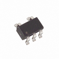
MAX1735EUK30+T Maxim Integrated Products, MAX1735EUK30+T Datasheet - Page 6

MAX1735EUK30+T
Manufacturer Part Number
MAX1735EUK30+T
Description
IC REG LDO NEG OUT 200MA SOT23-5
Manufacturer
Maxim Integrated Products
Datasheet
1.MAX1735EUK25-T.pdf
(10 pages)
Specifications of MAX1735EUK30+T
Regulator Topology
Negative Fixed or Adjustable
Voltage - Output
-3V, -1.25 ~ -5.5 V
Voltage - Input
-2.5 ~ -6.5 V
Voltage - Dropout (typical)
0.08V @ 200mA
Number Of Regulators
1
Current - Output
200mA (Min)
Current - Limit (min)
1.02A
Operating Temperature
-40°C ~ 85°C
Mounting Type
Surface Mount
Package / Case
SOT-23-5, SC-74A, SOT-25
Number Of Outputs
1
Polarity
Negative
Input Voltage Max
- 6.5 V
Output Voltage
- 1.25 V to - 5.5 V, - 3 V
Output Type
Adjustable, Fixed
Dropout Voltage (max)
0.24 V at - 200 mA
Output Current
200 mA
Line Regulation
0 % / V
Load Regulation
0.004 % / mA
Voltage Regulation Accuracy
1 %
Maximum Power Dissipation
0.571 W
Maximum Operating Temperature
+ 85 C
Mounting Style
SMD/SMT
Minimum Operating Temperature
- 40 C
Reference Voltage
- 1.25 V
Lead Free Status / RoHS Status
Lead free / RoHS Compliant
The MAX1735 is a low-dropout negative linear voltage
regulator. It features Dual Mode operation, allowing a
fixed -5.0V, -3.0V, or -2.5V output voltage or an
adjustable output from -1.25V to -5.5V. The regulator is
guaranteed to supply 200mA of output current. It fea-
tures 60dB power-supply rejection for noise-sensitive
applications and a low 85µA operating current that opti-
mizes it for battery-operated devices.
As Figure 1 illustrates, the device consists of an internal
-1.25V reference, an error amplifier, an N-channel
MOSFET, an internal precision-trimmed feedback volt-
age-divider, and a Dual Mode comparator.
The -1.25V reference is connected to the inverting input
of the error amplifier. The error amplifier compares the
reference voltage with the selected feedback voltage
and amplifies the difference. The error amplifier drives
the MOSFET to control the output voltage.
The feedback voltage for regulation is generated by
either an internal or external resistive voltage-divider
connected from OUT to SET. The internal Dual Mode
200mA, Negative-Output, Low-Dropout
Linear Regulator in SOT23
Figure 1. Functional Diagram
6
GND
_______________________________________________________________________________________
ON
OFF
ON
C
IN
Detailed Description
SHDN
IN
SHUTDOWN
LOGIC
-1.25V
V
REF
-270mV
Dual Mode
COMPARATOR
ERROR
AMPLIFIER
comparator selects the feedback path based on V
Connect SET to GND to use the internal feedback path,
setting the output voltage to the preset value. If an
external voltage-divider is used, see Output Voltage
Selection.
The MAX1735 features an N-channel MOSFET pass
transistor. Unlike similar designs using NPN bipolar
pass transistors, N-channel MOSFETs require extreme-
ly low drive currents, reducing overall quiescent cur-
rent. Also, NPN-based regulators consume still more
base current in dropout conditions when the pass tran-
sistor saturates. The MAX1735 does not suffer from
these problems, consuming only 125µA total current at
full load and in dropout.
The MAX1735 features Dual Mode operation, allowing for
a preset or adjustable output voltage. In preset voltage
mode, the output of the MAX1735 is set to -5.0V, -3.0V, or
-2.5V (see Ordering Information). Select this mode by
connecting SET to GND (Figure 2).
THERMAL
SENSOR
MAX1735
Internal N-Channel MOSFET
Output Voltage Selection
NMOS
PASS
TRANSISTOR
GND
OUT
SET
R2
R1
C
OUT
SET
.


