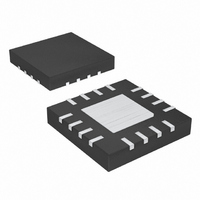
MAX8557ETE+T Maxim Integrated Products, MAX8557ETE+T Datasheet - Page 8

MAX8557ETE+T
Manufacturer Part Number
MAX8557ETE+T
Description
IC REG LDO 4A 16-TQFN
Manufacturer
Maxim Integrated Products
Datasheet
1.MAX8556EVKIT.pdf
(10 pages)
Specifications of MAX8557ETE+T
Regulator Topology
Positive Adjustable
Voltage - Output
0.5 ~ 3.4 V
Voltage - Input
1.43 ~ 3.6 V
Voltage - Dropout (typical)
0.1V @ 4A
Number Of Regulators
1
Current - Output
4A
Operating Temperature
-40°C ~ 85°C
Mounting Type
Surface Mount
Package / Case
16-TQFN Exposed Pad
Lead Free Status / RoHS Status
Lead free / RoHS Compliant
Current - Limit (min)
-
4A Ultra-Low-Input-Voltage
LDO Regulators
The MAX8556/MAX8557 feature an adjustable output
voltage from 0.5V to 3.4V. Set the output voltage using
an external resistor-divider from the output to GND with
FB connected to the center tap as shown in Figures 1
and 2. Choose R3 ≤ 1kΩ for light-load stability.
Determine R2 using the following equation:
where V
Capacitors are required at the MAX8556/MAX8557
inputs and outputs for stable operation over the full
temperature range and with load currents up to 4A.
Connect 2 x 10µF capacitors between IN and GND and
2 x 10µF low equivalent-series-resistance (ESR) capac-
itors between OUT and GND. The input capacitor (C
lowers the source impedance of the input supply. If the
MAX8556/MAX8557s’ input is close to the output of the
source supply, a smaller input capacitance can be
used. Otherwise, 2 x 10µF ceramic input capacitors are
recommended. The output capacitor’s (C
affects output noise and may affect output stability. Use
output capacitors with an ESR of 0.05Ω or less to
ensure stability and optimum transient dropout. For
good output transient performance, use the following
formula to select a minimum output capacitance:
The MAX8556/MAX8557 are designed to operate with
low-dropout voltages and low quiescent currents while
still maintaining low noise, good transient response,
and high AC rejection (see the Typical Operating
Characteristics for a plot of Power-Supply Rejection
Ratio (PSRR) vs. Frequency). When operating from
noisy sources, improved supply-noise rejection and
transient response can be achieved by increasing the
values of the input and output bypass capacitors and
through passive filtering techniques. The MAX8556/
MAX8557 load-transient response graphs (see the
8
_______________________________________________________________________________________
Noise, PSRR, and Transient Response
OUT
C
is the desired output voltage and V
OUT
R
2
Applications Information
=
= I
R
OUT(MAX)
3
Output Voltage Selection
Capacitor Selection and
x
⎛
⎜
⎝
V
V
OUT
FB
x 1µF/200mA
Regulator Stability
−
1
⎞
⎟
⎠
FB
OUT
is 0.5V.
) ESR
IN
)
Typical Operating Characteristics ) show two compo-
nents of the output response: a DC shift from the output
impedance due to the load current change, and the
transient response. A typical transient overshoot for a
step change in the load current from 40mA to 4A is
40mV. Use an output capacitance from 20µF to 120µF
to attenuate the overshoot.
Figure 1. MAX8556 Typical Application Circuit
Figure 2. MAX8557 Typical Application Circuit
2 x 10µF
2 x 10µF
SHUTDOWN
SHUTDOWN
POR
POK
1.425V TO 3.6V
1.7V TO 3.6V
C1
C1
V
V
IN
IN
100kΩ
100kΩ
ENABLED
ENABLED
R1
R1
1–6
1–6
12
18
12
18
IN
POR
EN
IN
POK
EN
MAX8557
MAX8556
N.C.
N.C.
U2
U1
15
15
GND
GND
OUT
OUT
FB
FB
7–11
13
14
7–11
13
14
R2
2kΩ
R3
1kΩ
R2
1.4kΩ
R3
1kΩ
1.5V AT 4A
1.2V AT 4A
V
V
OUT
OUT
C2
2 x 10µF
C2
2 x 10µF


